Web: Example for Enabling Multiple Tenants to Access the Enterprise Intranet Using the Sharing Mode Virtual Gateway That Shares the Public IP Address
Networking Requirements
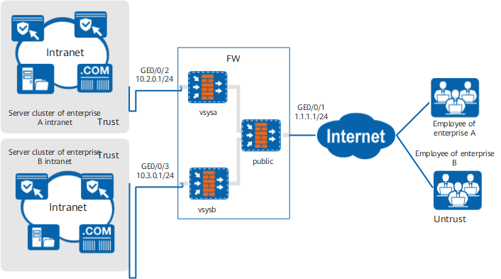
In the multi-tenant scenario, multiple virtual systems can be created on the FW. An SSL VPN gateway is created on the virtual system of each tenant, and each tenant can independently manage its own SSL VPN gateway. These virtual systems share one physical interface connected to the WAN, and each virtual system has its own virtual interface. Therefore, the virtual gateways in the virtual system need to share a public IP address to communicate over the WAN.
- The SSL connection is established between virtual gateways of enterprise A and enterprise B based on the shared public IP address, domain name, SSL version, cipher suite, and device certificate.
- Different virtual gateways of enterprise A and enterprise B are distinguished based on subdomains, so that different enterprise users can access respective enterprise network.
Data Planning
Item |
Data |
|---|---|
Interface |
Interface number: GigabitEthernet 0/0/1 IP address: 1.1.1.1/24 Security zone: untrust |
Interface number: GigabitEthernet 0/0/2 IP address: 10.2.0.1/24 Security zone: trust |
|
Interface number: GigabitEthernet 0/0/3 IP address: 10.3.0.1/24 Security zone: trust |
|
Public configuration |
Public IP address: 1.1.1.1 Public domain name: example.huawei.com SSL versions: TLS 1.1 and TLS 1.2 Cipher suites: aes256-sha and aes128-sha Local certificate: default |
Virtual gateway |
Enterprise A Name: gateway_A Type: sharing mode Gateway address: public IP address Domain name: example.huawei.com/companyA Maximum number of users: 150 Maximum number of concurrent users: 100 (The maximum number of concurrent users is controlled by the license. Therefore, configure this parameter based on actual situations.) |
Enterprise B Name: gateway_B Type: sharing mode Gateway address: public IP address Domain name: example.huawei.com/companyB Maximum number of users: 150 Maximum number of concurrent users: 100 (The maximum number of concurrent users is controlled by the license. Therefore, configure this parameter based on actual situations.) |
|
Web proxy |
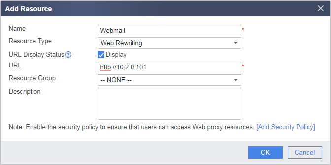
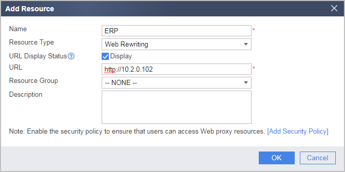
Web proxy resource of enterprise A Name: Webmail; Link: http://10.2.0.101 Name: ERP; Link: http://10.2.0.102 |
Web proxy resource of enterprise B Name: Webmail; Link: http://10.3.0.101 Name: ERP; Link: http://10.3.0.102 |
|
Network extension |
Enterprise A Network extension address pool: 172.16.1.1-172.16.1.100 Routing mode: Manual Intranet subnet accessible to network extension users: 10.2.0.0/16 |
Enterprise B Network extension address pool: 172.16.2.1-172.16.2.100 Routing mode: Manual Intranet subnet accessible to network extension users: 10.3.0.0/16 |
Configuration Roadmap
- Public parameters are configured in the root system. All sharing mode virtual gateways that share the public IP address establish SSL connections based on public parameters.
- The sharing mode virtual gateways that share the public IP address are created. (The virtual gateway type is configured based on actual situations. The SSL connection establishment modes vary depending on virtual gateway types and configurations.)
Except for subdomains and respective virtual system, configurations of virtual gateway gateway_A and virtual gateway gateway_B are basically the same. This section describes the configuration by taking gateway_A of enterprise A as an example.
Procedure
- Configure parameters in the root system.
- Configure interface corresponding to the public IP address.
Choose .
Click
 of GE0/0/1 and set the parameters as follows:
Security zone
untrust
IPv4
IP Address
1.1.1.1/24
Default gateway
1.1.1.2
- Click OK.
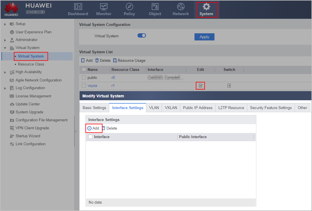
- Bind the virtual system and interface.
- Choose .
- Configure the interface GE0/0/2 connected to the vsysa, and click .
- Click the Allocate Interface and Set Public Interface tab, allocate interfaces to the virtual system, and configure parameters as shown in the following figure.
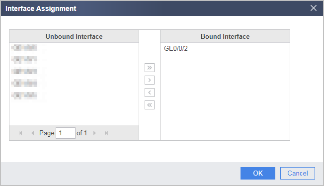
- Click OK.
- Configure public parameters.
Choose .
Set the following parameters.
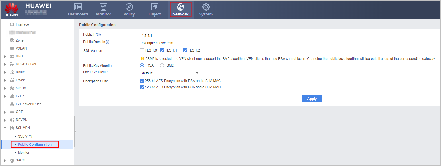
Click Apply.
- Configure interface corresponding to the public IP address.
- Configure virtual system vsysa.
- Create user groups and users.
Choose . Set the user group of user user0001 to /default/company_a, authentication type to local authentication, and password to User0001.
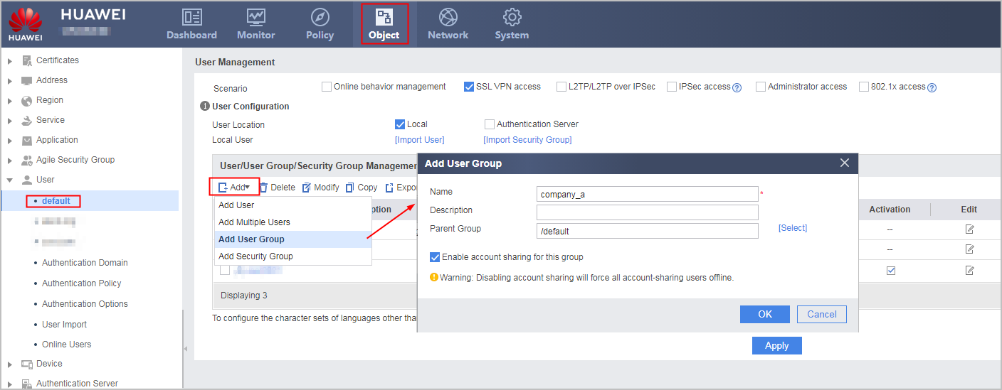
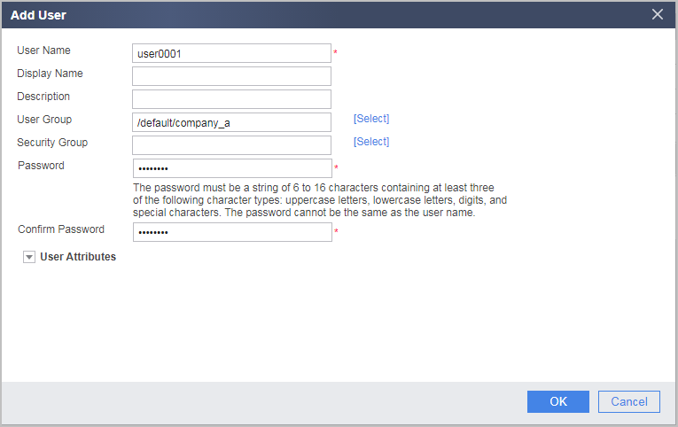
- Click OK.
Click Apply.
- Configure the interface connecting to the enterprise intranet.
- Choose .
- Configure interface GE0/0/2 and click. Configure the parameters as listed in the following table.
Security zone
trust
IPv4
IP Address
10.2.0.1/24
- Click OK.
- Configure sharing mode virtual gateway gateway_A.
- Choose .
Click Add and set the parameters as follows:
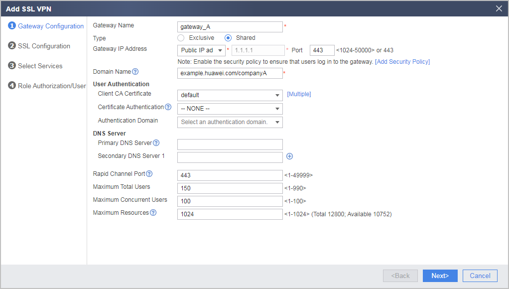

If the virtual gateway is bound to an authentication domain, the user name entered for a login should not carry the authentication domain information. If the user name carries an authentication domain name, the gateway considers the string following the at sign (@) as a part of the user name, not an authentication domain name. For example, if the virtual gateway has been bound to the authentication domain cce.com, you should enter user_0001, not user_0001@cce.com, as the user name.
- Click Next.
- Select the services to be enabled.
Select Web Proxy and Network Extension.
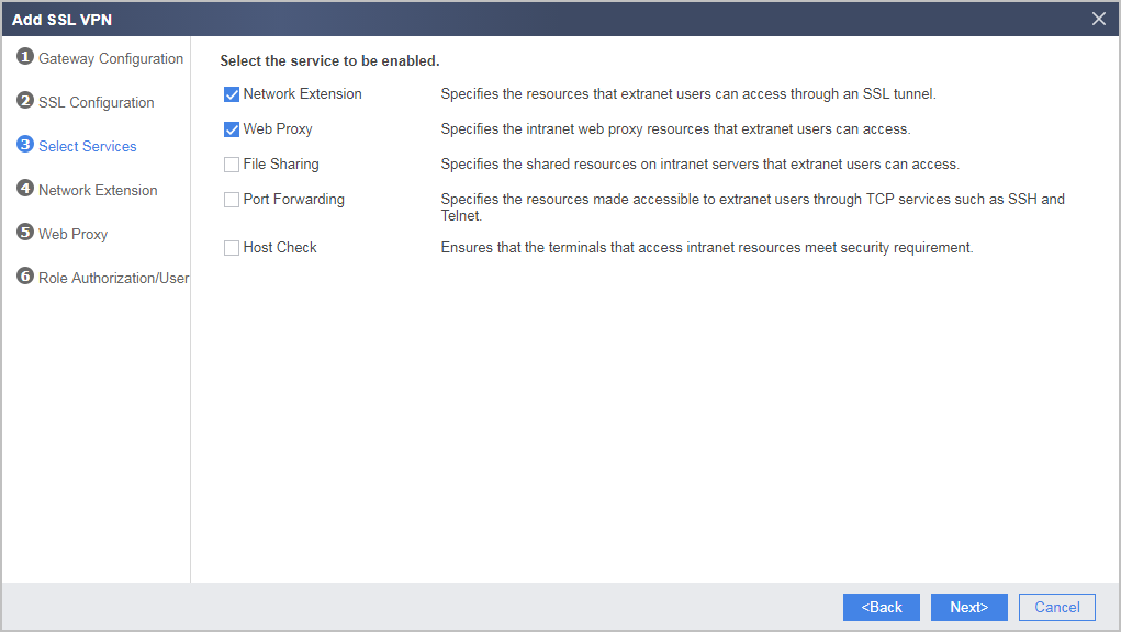
- Click Next.
- Configure the network extension function.
Set the Available IP Address Range and Accessible Private Network Segment List to the network extension function as follows:
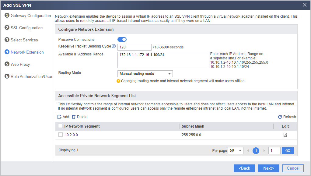
- Click Next.
- Configure the web proxy function and add resources Webmail and ERP.
Under Web Proxy Resource List, click Add.
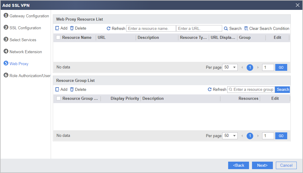
Add web proxy resource Webmail as follows:
- Click OK.
Repeat the preceding steps to add web proxy resource ERP as follows:
- Click OK.
- Click Next.
- Configure SSL VPN role authorization/users.
Under List of Authorized Roles, click Add.
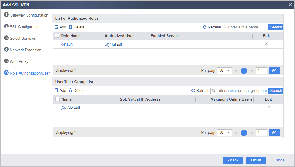
Add roles to the employee group of enterprise A and associate the roles with corresponding permissions.
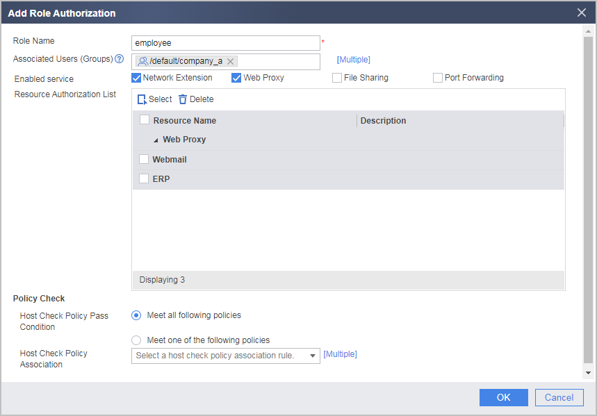
- Click OK.
- Click Finish.
- Create user groups and users.
Verifying the Configuration
- If you access the SSL VPN login page using the Internet Explorer browser, select the SSL version of the browser in . It is recommended that the SSL version of the Internet Explorer browser and the SSL version configured for the to-be-accessed virtual gateway be consistent or have an intersection.
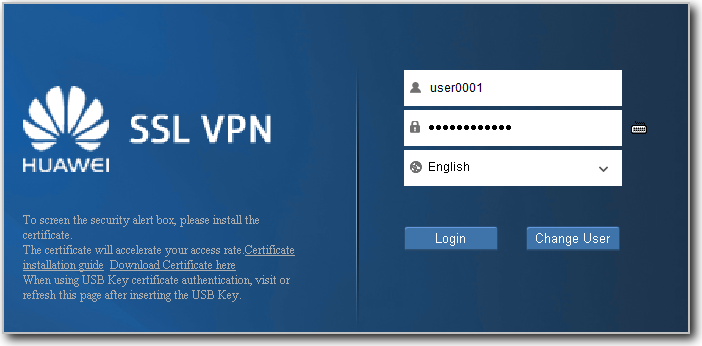
- Employee user0001 enter https://example.huawei.com/companyA in the Internet Explorer browser to access the SSL VPN login page. Upon the first access, install the controls as prompted.
- Enter the user name and password on the login page to log in to the SSL VPN gateway.
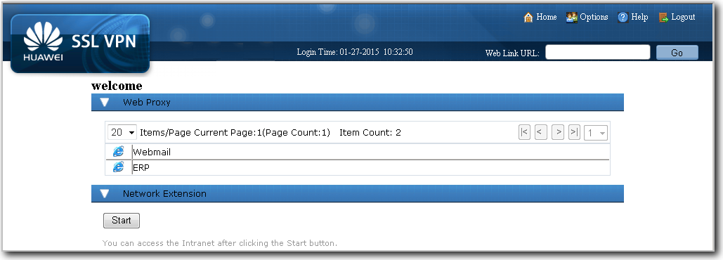
- If you log in to the SSL VPN gateway as the user user0001, you can use the web proxy and network extension services. Click Webmail and ERP to use the corresponding services. Click Start. The virtual adapter is automatically installed. After the virtual adapter obtains a virtual IP address, you can use the services as if you are using them on the LAN.
Configuration Scripts
#
interface GigabitEthernet0/0/1
 undo shutdown
 ip address 1.1.1.1 255.255.255.0
 gateway 1.1.1.2
#
firewall zone untrust
 set priority 5
 add interface GigabitEthernet0/0/1
#
interface GigabitEthernet0/0/2
 undo shutdown
 ip binding vpn-instance vsysa
 ip address 10.2.0.1 255.255.255.0
#
security-policy
rule name policy_1
  source-zone untrust
  destination-zone local
  destination-address 1.1.1.1 mask 255.255.255.255
  service https
  action permit
#
 v-gateway public-ip 1.1.1.1
 v-gateway public-domain example.huawei.com
 v-gateway public ssl version tlsv11 tlsv12
 v-gateway public ssl ciphersuit custom aes256-sha aes128-sha
#
switch vsys vsysa
#
vsys name vsysa 1
 assign interface GigabitEthernet0/0/2
 assign resource-class r0
 assign vlan 110
#
firewall zone trust
 add interface GigabitEthernet0/0/2
#
security-policy
 rule name policy_2
  source-zone local
  destination-zone trust
  destination-address 10.2.0.0 mask 255.255.0.0
  action permit
 rule name policy_3
  source-zone untrust
  destination-zone trust
  source-address range 172.16.1.1 172.16.1.100
  destination-address 10.2.0.0 mask 255.255.0.0
  action permit
#
 v-gateway gateway_a public-ip public example.huawei.com/companyA
 v-gateway gateway_a authentication-domain default
 v-gateway gateway_a alias gateway_a
#
#****BEGIN***gateway_a**1****#
v-gateway gateway_a
 basic
  ssl timeout 5
  ssl lifecycle 1440
 service
  web-proxy enable
  web-proxy web-link enable
  web-proxy proxy-resource Webmail http://10.2.0.101 show-link
  web-proxy proxy-resource ERP http://10.2.0.102 show-link
  network-extension enable
  network-extension keep-alive enable
  network-extension keep-alive interval 120
  network-extension netpool 172.16.1.1 172.16.1.100 255.255.255.0
  netpool 172.16.1.1 default
  network-extension mode manual
  network-extension manual-route 10.2.0.0 255.255.0.0
 security
  policy-default-action permit vt-src-ip
  certification cert-anonymous cert-field user-filter subject cn group-filter subject cn
  certification cert-anonymous filter-policy permit-all
  certification cert-challenge cert-field user-filter subject cn
  certification user-cert-filter key-usage any
  undo public-user enable
 hostchecker
 cachecleaner
 role
  role default condition all
  role employee condition all
  role employee network-extension enable
  role employee web-proxy enable
  role employee web-proxy resource ERP
  role employee web-proxy resource Webmail
#****END****#