Virtual System Traffic Sorting
This section describes how the FW forwards traffic of different virtual systems.
If no virtual systems are configured on the FW, the FW forwards packets based on policies and various tables (such as session, MAC address, and routing table) of the public system. After virtual systems are configured on the FW, each virtual system functions as a dedicated device and has its own policies and tables for packet processing. In this case, after receiving a packet, the FW must first determine the destination virtual system of the packet. This process is called traffic sorting.
The FW supports interface-based, VLAN-based, and VNI-based traffic sorting. When FW interfaces work at Layer 3, interface-based traffic sorting applies. When FW interfaces work at Layer 2, VLAN-based traffic sorting applies. When virtual systems and VXLAN work together, VXLAN Network Identifier (VNI)-based traffic sorting applies.
Interface-based Traffic Sorting
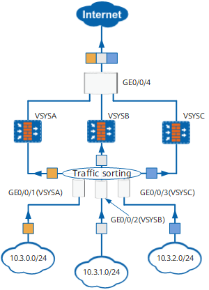
After an interface is bound to a virtual system, all packets received at this interface belong to the bound virtual system, and the FW processes the packets based on the configuration of the virtual system.
In Figure 1, the three virtual systems, VSYSA, VSYSB, and VSYSC, have their dedicated inside interfaces, which are respectively GigabitEthernet 0/0/1, GigabitEthernet 0/0/2, and GigabitEthernet 0/0/3. After receiving packets, the FW forwards them to their virtual systems for routing and policy matching.
VLAN-based Traffic Sorting
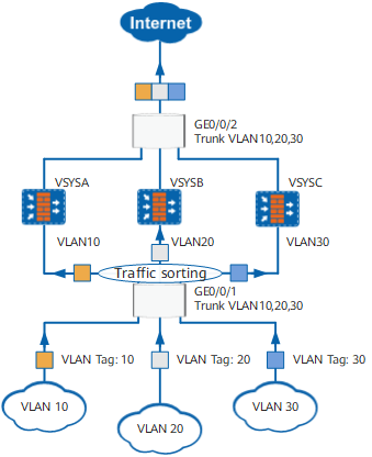
If a VLAN is bound to a virtual system, the FW forwards packets from this VLAN to the bound virtual system.
In Figure 2, the inside interface GigabitEthernet 0/0/1 of the FW is a Layer-2 trunk interface and is configured to permit packets from VLAN10, VLAN20, and VLAN30, which are bound to VSYSA, VSYSB, and VSYSC respectively. After receiving a packet on GigabitEthernet 0/0/1, the FW checks the VLAN tag carried in the packet header to determine the source VLAN of the packet and then forwards the packet to the virtual system to which the VLAN is bound.
After the packet enters the virtual system, the FW checks the MAC address table to obtain the outgoing interface and then forwards or discards the packet based on the inter-zone policy.
VNI-based Traffic Sorting
If a VNI is bound to a virtual system, the FW forwards packets from this VXLAN to the bound virtual system.
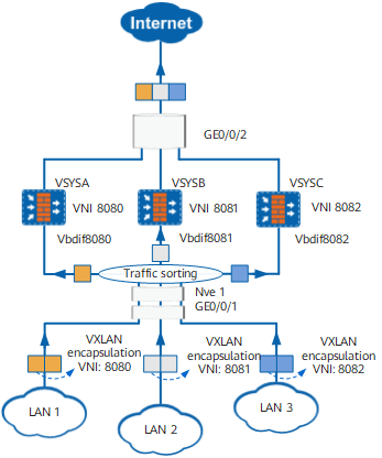
As shown in Figure 3, after identifying that the destination IP address of a received packet is the IP address of Nve1, GigabitEthernet 0/0/1 of the FW sends the packet to Nve1 for decapsulation. According to the VNI in the VXLAN header and binding between the VNI and virtual system, the FW determines the virtual system to which the packet will be sent after decapsulating the packet.
After the packet enters the virtual system, the virtual system searches its routing table for the outbound interface to determine the inter-zone relationship of the inbound and outbound interfaces, and then forwards or discards the packet based on the inter-zone policy.

After the VNI and virtual system are bound, the corresponding Vbdif interface is assigned to the corresponding virtual system along with the VNI.
In the virtual system, the inbound interface of the packet is a Vbdif interface.