Communication Between a Virtual System and the Public System
The packet forwarding process is slightly different for the access from a virtual system to the public system and the access from the public system to a virtual system.
Access from a Virtual System to the Public System
As shown in Figure 1, users in the network segment 10.3.0.0/24 in virtual system vsysa access the Internet server 3.3.3.3 through the WAN interface GE0/0/1.
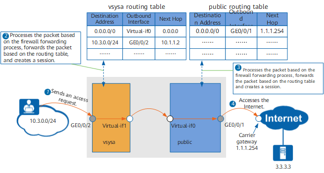
The virtual system initiates an access request to the public system. The request packet enters the virtual system. The virtual system processes the packet based on the firewall forwarding process. Then, the packet enters the public system. The public system processes the packet based on the firewall forwarding process. The detailed process is as follows:
- The client initiates a connection to the server.
The first packet arrives at the FW and is sent to vsysa based on the interface. vsysa processes the packet based on the firewall forwarding process, including matching the blacklist, looking up the routing table, performing NAT, and matching a security policy. If the packet is denied at any step, vsysa discards the packet, and the process ends. If the packet passes all the steps, vsysa forwards the packet to the public system. At the same time, vsysa creates the following session for the connection:
<FW> display firewall session table verbose vsys vsysa destination global 3.3.3.3
 Current Total Sessions : 1
 icmp  VPN: vsysa --> public  ID: a48f34469c9a08f48570d0de4
 Zone: trust --> untrust  TTL: 00:00:20  Left: 00:00:01
 Recv Interface: GigabitEthernet 0/0/2
 Interface: Virtual-if1  NextHop: 0.0.0.0
 <--packets: 5 bytes: 60 --> packets: 5 bytes: 420
 10.3.0.2:43999 --> 3.3.3.3:2048 PolicyName: vsysa_to_internet
After receiving the packet on the virtual interface Virtual-if0, the public system processes the packet based on the firewall forwarding process, including matching the blacklist, looking up the routing table, performing NAT, and matching a security policy. If the packet is denied at any step, the public system discards the packet, and the process ends. If the packet passes all the steps, the public system forwards the packet to the server. At the same time, the public system creates the following session for the connection:
<FW> display firewall session table verbose destination global 3.3.3.3
 Current Total Sessions : 1
 icmp  VPN: public --> public  ID: a48f34995b4d0358b570d0f72
 Zone: trust --> untrust  TTL: 00:00:20  Left: 00:00:01
 Recv Interface: Virtual-if0
 Interface: GigabitEthernet 0/0/1  NextHop: 1.1.1.254  MAC: 00e0-4c88-56cb
 <--packets: 5 bytes: 60 --> packets: 5 bytes: 420
 10.3.0.2:43999[1.1.1.1:2048] --> 3.3.3.3:2048 PolicyName: to_internet
- The packet is forwarded through the router and arrives at the server.
As both the virtual system and public system need to process the packet based on the firewall forwarding process, policies and routes must be configured for the virtual system and public system.
- The key of policy configuration is to determine the source and destination security zones.
Item
Description
Virtual system
Source zone
Security zone to which the inbound interface of the packet belongs, that is, security zone to which GE0/0/2 belongs in Figure 1
Destination zone
Security zone to which the virtual interface of the virtual system belongs, that is, security zone to which Virtual-if1 belongs in Figure 1
Public system
Source zone
Security zone to which Virtual-if0 belongs
Destination zone
Security zone to which the outbound interface of the packet belongs, that is, security zone to which GE0/0/1 belongs in Figure 1
- The route configuration is slightly different from virtual and public systems.
Item
Description
Virtual system
Forward route
Route to the Internet. As the packet must be forwarded to the Internet through the public system, the route from the virtual system to the public system is required. The route from the virtual system to the public system can only be a static route. Different from common static routes, this static route does not need the next hop or outbound interface. Instead, you must specify the public system as the destination virtual system for the route.
For the network in Figure 1, you can configure the static route as follows:
<sysname> system-view
[sysname] switch vsys vsysa
<sysname-vsysa> system-view
[sysname-vsysa] ip route-static 0.0.0.0 0.0.0.0 public
NOTE:IPv6 routing configuration does not support virtualization. When an IPv6 virtual system accesses the public system, run the ipv6 route-static vpn-instance vsysa dest-ipv6-address prefix-length public command in the system view of the public system to configure a route from vsysa to the public system.
Return route
Route to the intranet. It can be a dynamic route (such as OSPF) or a static route.
For the network in Figure 1, you can configure a static route to the intranet as follows (10.1.1.2 is the next hop from the FW to the intranet):
<sysname> system-view
[sysname] switch vsys vsysa
<sysname-vsysa> system-view
[sysname-vsysa] ip route-static 10.3.0.0 255.255.255.0 10.1.1.2
NOTE:IPv6 routing configuration does not support virtualization. When an IPv6 virtual system accesses the public system, run the ipv6 route-static vpn-instance vsysa dest-ipv6-address prefix-length interface-type interface-number [ nexthop-ipv6-address ] command in the system view of the public system to configure a route from vsysa to the intranet.
Public system
Forward route
Route to the Internet. It can be a dynamic route (such as OSPF) or a static route.
For the network in Figure 1, you can configure a static route to the Internet as follows (1.1.1.254 is the next hop from the FW to the Internet):
<sysname> system-view
[sysname] ip route-static 0.0.0.0 0.0.0.0 1.1.1.254
NOTE:When an IPv6 virtual system accesses the public system, run the ipv6 route-static dest-ipv6-address prefix-length interface-type interface-number [ nexthop-ipv6-address ] command in the system view of the public system to configure a route from the public system to the Internet.
Return route
In the public system, you do not need to configure return routes for the packets replied by the server. After matching the session table, the packets replied by the server are directly forwarded to the virtual system. This route configuration is different from that for forwarding within one virtual system.
Access from the Public System to a Virtual System
As shown in Figure 2, an Internet user accesses a server in the virtual system vsysa through the WAN interface GE0/0/1 in the public system.
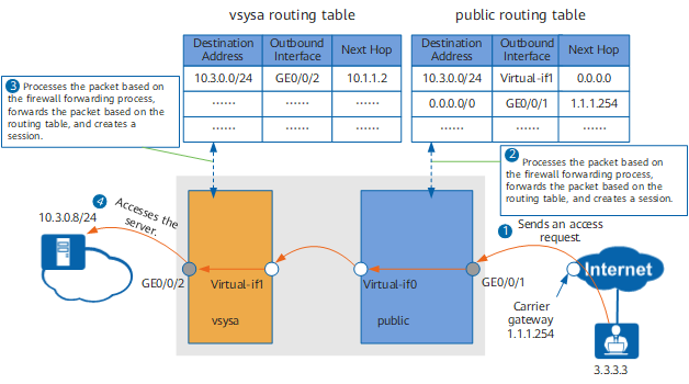
The public system initiates an access request to the virtual system. The request packet enters the public system and then the virtual system. The virtual and public systems process the packet in the way similar to that for Access from a Virtual System to the Public System.
The route and policy configuration for the virtual and public systems is different from that for Access from a Virtual System to the Public System. The details are as follows:
- The following table shows the source and destination security zones for the access from the public system to the virtual system.
Item
Description
Public system
Source zone
Security zone to which the inbound interface of the packet belongs, that is, security zone to which GE0/0/1 belongs in Figure 2
Destination zone
Security zone to which Virtual-if0 belongs
Virtual system
Source zone
Security zone to which the virtual interface of the virtual system belongs, that is, security zone to which Virtual-if1 belongs in Figure 2
Destination zone
Security zone to which the outbound interface of the packet belongs, that is, security zone to which GE0/0/2 belongs in Figure 2
- The following table shows the route configuration for the virtual and public system for the access from the public system to the virtual system.
Item
Description
Public system
Forward route
Route to the server on the intranet. As the packet must be forwarded to the server through the virtual system, the route from the public system to the virtual system is required. The route from the public system to the virtual system can only be a static route. Different from common static routes, this static route does not need the next hop or outbound interface. Instead, you must specify the virtual system of the server as the destination virtual system for the route.
For the network in Figure 2, you can configure the static route as follows:
<sysname> system-view
[sysname] ip route-static 10.3.0.0 255.255.255.0 vpn-instance vsysa
NOTE:To allow the Internet user to access the server on the intranet, you must configure NAT Server in vsysa or the public system to translate addresses.
If you configure NAT Server in the public system, the public system translates the destination address of the packet from a public address to a private one before looking up the routing table. Therefore, the destination address of the route configured for the public system must be the private address of the server.
If you configure NAT Server in the virtual system, the public system forwards the packet to the virtual system, and the virtual system translates the destination address of the packet from a public address to a private one. Therefore, the destination address of the route configured for the public system must be the public address of the server.
NOTE:When an IPv6 virtual system accesses the public system, run the ipv6 route-static dest-ipv6-address prefix-length vpn-instance vsysa command in the system view of the public system to configure a route from the public system to vsysa.
Return route
Route to the Internet. It can be a dynamic route (such as OSPF) or a static route.
For the network in Figure 2, you can configure a static route to the Internet as follows (1.1.1.254 is the next hop from the FW to the Internet):
<sysname> system-view
[sysname] ip route-static 0.0.0.0 0.0.0.0 1.1.1.254
NOTE:When the IPv6 public system accesses a virtual system, run the ipv6 route-static dest-ipv6-address prefix-length interface-type interface-number [ nexthop-ipv6-address ] command in the system view of the public system to configure a route from the public system to the Internet.
Virtual system
Forward route
Route to the server on the intranet. It can be a dynamic route (such as OSPF) or a static route.
For the network in Figure 2, you can configure a static route to the intranet as follows (10.1.1.2 is the next hop from the FW to the intranet):
<sysname> system-view
[sysname] switch vsys vsysa
<sysname-vsysa> system-view
[sysname-vsysa] ip route-static 10.3.0.0 255.255.255.0 10.1.1.2
NOTE:IPv6 routing configuration does not support virtualization. When the IPv6 public system accesses a virtual system, run the ipv6 route-static vpn-instance vsysa dest-ipv6-address prefix-length interface-type interface-number [ nexthop-ipv6-address ] command in the system view of the public system to configure a route from vsysa to the intranet.
Return route
In the virtual system, you do not need to configure return routes for the packets replied by the server. After matching the session table in the virtual system, the packets replied by the server are directly forwarded to the public system. This route configuration is different from that for forwarding within one virtual system.