CLI: Example for Enabling an IPv6 User to Access an IPv4 Server
Dynamic NAT64 mapping applies when the IPv6 network accesses the IPv4 network.
Networking Requirements
As shown in Figure 1, the FW supports the IPv6/IPv4 dual stack and is connected to an IPv6 network and an IPv4 network.

When the NAT64 is deployed with DNS64. The DNS64 device provides domain name resolution. The prefix and prefix length set on the DNS64 device are the same as those on the FW.
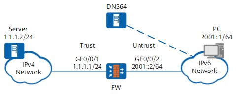
The PC on the IPv6 network can access the server on the IPv4 network using URL www.example.com.
Procedure
- Configure FW.
# Set an IPv4 address for GigabitEthernet 0/0/1.
<FW> system-view
[FW] interface GigabitEthernet 0/0/1
[FW-GigabitEthernet 0/0/1] ip address 1.1.1.1 24
[FW-GigabitEthernet 0/0/1] quit
# Enable the IPv6 packet forwarding function.
[FW] ipv6# Set an IPv6 address for GigabitEthernet 0/0/2.
[FW] interface GigabitEthernet 0/0/2
[FW-GigabitEthernet 0/0/2] ipv6 enable
[FW-GigabitEthernet 0/0/2] ipv6 address 2001::2 64
# Enable NAT64 on GigabitEthernet 0/0/2.
[FW-GigabitEthernet 0/0/2] nat64 enable
[FW-GigabitEthernet 0/0/2] quit
# Assign GigabitEthernet 0/0/1 to the Trust zone.
[FW] firewall zone trust
[FW-zone-trust] add interface GigabitEthernet 0/0/1
[FW-zone-trust] quit
# Assign GigabitEthernet 0/0/2 to the Untrust zone.
[FW] firewall zone untrust
[FW-zone-untrust] add interface GigabitEthernet 0/0/2
[FW-zone-untrust] quit
# Configure a security policy.
[FW] security-policy
[FW-policy-security] rule name policy_sec_1
[FW-policy-security-rule-policy_sec_1] source-zone untrust
[FW-policy-security-rule-policy_sec_1] destination-zone trust
[FW-policy-security-rule-policy_sec_1] source-address 2001:: 64
[FW-policy-security-rule-policy_sec_1] action permit
[FW-policy-security-rule-policy_sec_1] quit
# Set the IPv6 prefix to 3001::/96.
[FW] nat64 prefix 3001:: 96 In the following example, the NAT64 prefix is 3001::96.
# Configure IPv4 NAT address pool addressgroup1 whose addresses range from 1.1.1.6 through 1.1.1.10. The addresses in this NAT address pool are the IPv4 addresses of resulting packets.
[FW] nat address-group addressgroup1
[FW-address-group-addressgroup1] mode pat
[FW-address-group-addressgroup1] section 1 1.1.1.6 1.1.1.10
[FW-address-group-addressgroup1] quit
# Configure a dynamic NAT64 mapping between the Trust and Untrust zones.
[FW] nat-policy
[FW-policy-nat] rule name policy_nat64
[FW-policy-nat-rule-policy_nat64] nat-type nat64
[FW-policy-nat-rule-policy_nat64] source-zone untrust
[FW-policy-nat-rule-policy_nat64] destination-zone trust
[FW-policy-nat-rule-policy_nat64] source-address 2001:: 64
[FW-policy-nat-rule-policy_nat64] action source-nat address-group addressgroup1
[FW-policy-nat-rule-policy_nat64] quit
[FW-policy-nat] quit
- Configure the DNS64 device.
# Set the IPv6 prefix of the DNS64 device to 3001::/96, which is the same as the NAT64 prefix of the FW.
# The IP connectivity between the DNS64 device and the PC, and between the DNS64 device and the server is ensured.
- Configure the PC IPv6 address, the route and the DNS server. (The method of setting IPv6 address, route and DNS server varies depending on the operating system of the PC. The setting method is omitted here.)
# Set the PC IPv6 address to 2001::1/24, which is on the same subnet as GigabitEthernet 0/0/2 of FW.
# Set a static route from the PC to the FW. The destination address is prefix 3001::/96, and the next-hop address is 2001::2.
# Set the DNS server of the PC to the IPv6 address of the DNS64 device.
- Configure the server IPv4 address. (The method of setting IPv4 address varies depending on the operating system of the server. The setting method is omitted here.)
# Set the server IPv4 address to 1.1.1.2/24, which is on the same subnet as GigabitEthernet 0/0/1 of FW.
Verification
# After the configuration is complete, run the ping www.example.com command on the PC.
c:\ ping www.example.com
Pinging 3001::0101:102 with 32 bytes of data:

Reply from 3001::0101:102: time=23ms
Reply from 3001::0101:102: time=6ms
Reply from 3001::0101:102: time=12ms
Reply from 3001::0101:102: time=33ms

Ping statistics for 3001::0101:102:
    Packets: Sent = 4, Received = 4, Lost = 0 (0% loss),
Approximate round trip times in milli-seconds:
    Minimum = 6ms, Maximum = 33ms, Average = 18ms
The IPv4 address of the server can be pinged through from the PC.
# In any view of FW, run the display firewall ipv6 session table command to verify information about the NAT64 session table.
<FW> display firewall ipv6 session table
 Slot: 6 CPU: 1
NAT64: icmp6 VPN: public --> public  2001::1.44152[1.1.1.10:10296] --> 3001::0101:102.2048[1.1.1.2:2048]
According to the NAT64 session table information, you can obtain the mapping of IPv6 addresses and IPv4 addresses.
Configuration Scripts
Configuration script for the FW:
#
 sysname FW
#
 ipv6
#
interface GigabitEthernet 0/0/1
 ip address 1.1.1.1 255.255.255.0
#
interface GigabitEthernet 0/0/2
 ipv6 enable
 nat64 enable
 ipv6 address 2001::2/64
#
nat address-group addressgroup1
 mode pat
 section 1 1.1.1.6 1.1.1.10
#
firewall zone trust
 set priority 85
 add interface GigabitEthernet 0/0/1
#
firewall zone untrust
 set priority 5
 add interface GigabitEthernet 0/0/2
#
 nat64 prefix 3001:: 96
#
security-policy
  rule name policy_sec_1
    source-zone untrust
    destination-zone trust
    source-address 2001:: 64
    action permit
#
nat-policy
  rule name policy_nat64
    source-zone untrust
    destination-zone trust
    nat-type nat64
    source-address 2001:: 64
    action source-nat address-group addressgroup1
#
return