CLI: Example for Configuring the Interworking with the Agile Controller in Dual-device Off-line Mode
Typical Networking
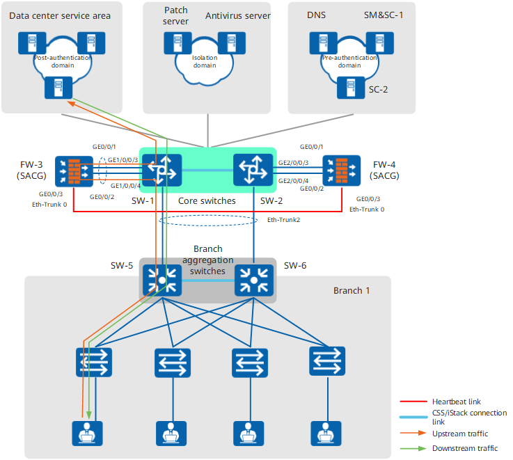
As shown in Figure 1, firewalls are attached to core switches as the hardware SACGs of the Agile Controller. When users in branch 1 access the data center service area, the firewalls work with the Agile Controller to control user access as follows:
- To ensure the security of the service system and prevent external users or insecure terminal hosts from accessing the service system, only the users who have passed the identify authentication and terminal security check are allowed to access the service system.
- The service system is the core network resource, and employees are allowed to access the system only in working hours.
- The solution deployment has the minimum impact on the current network. The service first principle is applied to the entire network to ensure service continuity in the case that the access control system fails.
The data center network is logically divided into the pre-authentication domain, isolation domain, and post-authentication domain:
- The pre-authentication domain is accessible to unauthenticated terminal hosts, and comprises the DNS, external authentication source, SC, and SM.
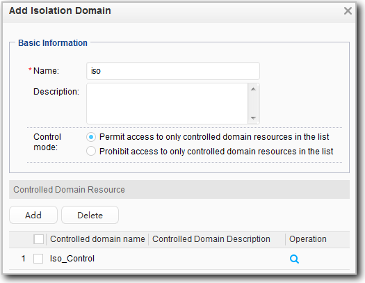
- The isolation domain is accessible to terminal hosts that pass the identity authentication but not the security authentication, and comprises the patch server and anti-virus server.
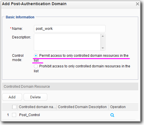
- The post-authentication domain is accessible for terminal hosts that have passed identity and security authentication. In this case, this domain is the data center service area.
Service Planning
Firewall IP Address Planning
No. |
Local Device |
Local Interface |
Local IP Address |
Peer Device |
Peer Interface |
Peer IP Address |
|---|---|---|---|---|---|---|
1 |
FW-3 |
GE0/0/1 |
10.4.1.2/29 VRID: 1 VIP: 10.4.1.1 |
SW-1 |
VLANIF101 |
10.4.1.4/29 |
2 |
FW-3 |
GE0/0/2 |
10.5.1.2/29 VRID: 2 VIP: 10.5.1.1 |
SW-1 |
VLANIF102 |
10.5.1.4/29 |
3 |
FW-3 |
GE0/0/3 |
10.10.10.1/24 |
FW-4 |
GE0/0/3 |
10.10.10.2/24 |
4 |
FW-4 |
GE0/0/1 |
10.4.1.3/29 VRID: 1 VIP: 10.4.1.1 |
SW-2 |
VLANIF101 |
10.4.1.4/29 |
5 |
FW-4 |
GE0/0/2 |
10.5.1.3/29 VRID: 2 VIP: 10.5.1.1 |
SW-2 |
VLANIF102 |
10.5.1.4/29 |
6 |
FW-4 |
GE0/0/3 |
10.10.10.2/24 |
FW-1 |
GE0/0/3 |
10.10.10.1/24 |
Firewall Security Zone Planning
No. |
Security Zone |
Security Zone Priority |
Included Interface |
Remarks |
|---|---|---|---|---|
1 |
untrust |
5 |
GE0/0/2 |
Downstream service interface |
2 |
trust |
100 |
GE0/0/1 |
Upstream service interface |
3 |
dmz |
50 |
GE0/0/3 |
Heartbeat interface |
Service Controller Data Planning
Item |
Data |
Remarks |
|---|---|---|
Service Controller 1 |
IP address: 192.168.1.2/24 Port: 3288 Shared key: TSM_Security |
The port and shared key configured on the FW must be consistent with those configured on the Service Controller. If an unauthenticated terminal user attempts to access the Web server in the post-authentication domain in the case that the Web push function is configured on the FW, the FW pushes the Web authentication page to the terminal user, facilitating terminal user's identity authentication on the web page. |
Service Controller 2 |
IP address: 192.168.1.3/24 Port: 3288 Shared key: TSM_Security |
Same as Service Controller 1. |
Service Manager |
Login address: https://192.168.1.2:8443 User name: admin Password: Admin@123 |
The Service Manager and Service Controller 1 are installed on the same server. You need to log in to the Service Manager to configure the Agile Controller. |
Network segment on which the terminal user resides |
10.8.1.0/24 |
Network segment of users in branch 1. |
Post-authentication domain |
10.1.1.4 10.1.1.5 |
Add the servers in the data center service area to the post-authentication domain and apply user accounts in branch 1. |
Isolation domain |
Patch server: 192.168.2.3/24 Antivirus server: 192.168.2.5/24 |
Add the patch server and antivirus server to the isolation domain and apply user accounts in branch 1. |
Pre-authentication domain |
DNS server: 192.168.3.3/24 Service Controller 1: 192.168.1.2/24 Service Controller 2: 192.168.1.3/24 |
Add the DNS server and Service Controllers to the pre-authentication domain. |
Procedure
- Configure IP addresses for interfaces and assign the interfaces to security zones.
# # Configure IP addresses for the interfaces of FW-3.
<sysname> system-view
[sysname] sysname FW-3
[FW-3] interface GigabitEthernet 0/0/1
[FW-3-GigabitEthernet0/0/1] description SACG1_To_Coreswitch1_GE1/1/0/3
[FW-3-GigabitEthernet0/0/1] ip address 10.4.1.2 29
[FW-3-GigabitEthernet0/0/1] quit
[FW-3] interface GigabitEthernet 0/0/2
[FW-3-GigabitEthernet0/0/2] description SACG1_To_Coreswitch1_GE1/1/0/4
[FW-3-GigabitEthernet0/0/2] ip address 10.5.1.2 29
[FW-3-GigabitEthernet0/0/2] quit
[FW-3] interface GigabitEthernet 0/0/3
[FW-3-GigabitEthernet0/0/3] description hrp_interface
[FW-3-GigabitEthernet0/0/3] ip address 10.10.10.1 24
[FW-3-GigabitEthernet0/0/3] quit
# # Configure IP addresses for the interfaces of FW-4.
<sysname> system-view
[sysname] sysname FW-4
[FW-4] interface GigabitEthernet 0/0/1
[FW-4-GigabitEthernet0/0/1] description SACG2_To_Coreswitch2_GE2/1/0/3
[FW-4-GigabitEthernet0/0/1] ip address 10.4.1.3 29
[FW-4-GigabitEthernet0/0/1] quit
[FW-4] interface GigabitEthernet 0/0/2
[FW-4-GigabitEthernet0/0/2] description SACG2_To_Coreswitch2_GE2/1/0/4
[FW-4-GigabitEthernet0/0/2] ip address 10.5.1.3 29
[FW-4-GigabitEthernet0/0/2] quit
[FW-4] interface GigabitEthernet 0/0/3
[FW-4-GigabitEthernet0/0/3] description hrp_interface
[FW-4-GigabitEthernet0/0/3] ip address 10.10.10.2 24
[FW-4-GigabitEthernet0/0/3] quit
# Assign the interfaces of FW-3 to appropriate security zones.
[FW-3] firewall zone trust
[FW-3-zone-trust] add interface GigabitEthernet 0/0/1
[FW-3-zone-trust] quit
[FW-3] firewall zone untrust
[FW-3-zone-untrust] add interface GigabitEthernet 0/0/2
[FW-3-zone-untrust] quit
[FW-3] firewall zone dmz
[FW-3-zone-dmz] add interface GigabitEthernet 0/0/3
[FW-3-zone-dmz] quit
# Assign the interfaces of FW-4 to appropriate security zones.
[FW-4] firewall zone trust
[FW-4-zone-trust] add interface GigabitEthernet 0/0/1
[FW-4-zone-trust] quit
[FW-4] firewall zone untrust
[FW-4-zone-untrust] add interface GigabitEthernet 0/0/2
[FW-4-zone-untrust] quit
[FW-4] firewall zone dmz
[FW-4-zone-dmz] add interface GigabitEthernet 0/0/3
[FW-4-zone-dmz] quit
- Configure static routes.
# On FW-3, configure a static route to guide traffic back to the core switch.
[FW-3] ip route-static 0.0.0.0 0.0.0.0 10.4.1.4# On FW-4, configure a static route to guide traffic back to the core switch.
[FW-4] ip route-static 0.0.0.0 0.0.0.0 10.4.1.4 - Configure link-group.
# On FW-3, configure link-group 1 and add upstream and downstream service interfaces to the link-group.
[FW-3] interface GigabitEthernet 0/0/1
[FW-3-GigabitEthernet0/0/1] link-group 1
[FW-3-GigabitEthernet0/0/1] quit
[FW-3] interface GigabitEthernet 0/0/2
[FW-3-GigabitEthernet0/0/2] link-group 1
[FW-3-GigabitEthernet0/0/2] quit
# On FW-4, configure link-group 1 and add upstream and downstream service interfaces to the link-group.
[FW-4] interface GigabitEthernet 0/0/1
[FW-4-GigabitEthernet0/0/1] link-group 1
[FW-4-GigabitEthernet0/0/1] quit
[FW-4] interface GigabitEthernet 0/0/2
[FW-4-GigabitEthernet0/0/2] link-group 1
[FW-4-GigabitEthernet0/0/2] quit
- Configure hot standby.
# Configure VRRP group 1 on the upstream interface GE0/0/1 of FW-3, setting its state to Active.
[FW-3] interface GigabitEthernet 0/0/1
[FW-3-GigabitEthernet0/0/1] vrrp vrid 1 virtual-ip 10.4.1.1 active
[FW-3-GigabitEthernet0/0/1] quit
# Configure VRRP group 2 on the downstream interface GE0/0/2 of FW-3, setting its state to Active.
[FW-3] interface GigabitEthernet 0/0/2
[FW-3-GigabitEthernet0/0/2] vrrp vrid 2 virtual-ip 10.5.1.1 active
[FW-3-GigabitEthernet0/0/2] quit
# Designate GE0/0/3 as the heartbeat interface of FW-3, and enable hot standby.
[FW-3] hrp interface GigabitEthernet 0/0/3 remote 10.10.10.2
[FW-3] hrp enable
# Configure VRRP group 1 on the upstream interface GE0/0/1 of FW-4, setting its state to Active.
[FW-4] interface GigabitEthernet 0/0/1
[FW-4-GigabitEthernet0/0/1] vrrp vrid 1 virtual-ip 10.4.1.1 standby
[FW-4-GigabitEthernet0/0/1] quit
# Configure VRRP group 2 on the downstream interface GE0/0/2 of FW-4, setting its state to Active.
[FW-4] interface GigabitEthernet 0/0/2
[FW-4-GigabitEthernet0/0/2] vrrp vrid 2 virtual-ip 10.5.1.1 standby
[FW-4-GigabitEthernet0/0/2] quit
# Designate GE0/0/3 as the heartbeat interface of FW-4, and enable hot standby.
[FW-4] hrp interface GigabitEthernet 0/0/3 remote 10.10.10.1
[FW-4] hrp enable

After hot standby is configured, you only need to configure security policies and SACG on the active device FW-3. The configuration on FW-3 is automatically backed up on FW-4.
- Disable the stateful inspection function.
HRP_M[FW-3] undo firewall session link-state check - Configure security policies.
# Configure a Local-Trust security policy to allow the communication between the FW and Service Controller.
HRP_M[FW-3] security-policy
HRP_M[FW-3-security-policy] rule name sc_to_sacg
HRP_M[FW-3-security-policy-sc_to_sacg] source-zone trust local
HRP_M[FW-3-security-policy-sc_to_sacg] destination-zone local trust
HRP_M[FW-3-security-policy-sc_to_sacg] action permit
HRP_M[FW-3-security-policy-sc_to_sacg] quit
# Configure the policy for the Local-Untrust interzone. In this way, the FW can push the web-based authentication page to the user.
HRP_M[FW-3-security-policy] rule name sacg_to_client
HRP_M[FW-3-security-policy-sacg_to_client] source-zone local
HRP_M[FW-3-security-policy-sacg_to_client] destination-zone untrust
HRP_M[FW-3-security-policy-sacg_to_client] action permit
HRP_M[FW-3-security-policy-sacg_to_client] quit
HRP_M[FW-3-security-policy] quit
- Configure the interworking with the Agile Controller.
# Enter the view of configuring the FW to interwork with the Agile Controller, and specify the number of the default ACL rule group.
If ACLs 3099 to 3999 are in use, delete them before configuring the interworking with the Agile Controller. Otherwise, conflicts occur when the FW generates ACL rules.
HRP_M[FW-3] right-manager server-group
HRP_M[FW-3-rightm] default acl 3099
# Add the Service Controller to the FW. Then the FW can interwork with the Service Controller. Because two Service Controllers are deployed, you must run the server ip command twice to add the two Service Controllers.
The port and shared key in the server ip command must be the same as those on the Service Controller. Otherwise, the FW cannot interwork with the Service Controller, and the SACG interworking function is unavailable.
HRP_M[FW-3-rightm] server ip 192.168.1.2 port 3288 shared-key TSM_Security
HRP_M[FW-3-rightm] server ip 192.168.1.3 port 3288 shared-key TSM_Security
# Configure Web authentication. If an unauthenticated terminal user attempts to access the network, the FW automatically pushes the Web authentication page to the terminal user. Therefore, the terminal user can be authenticated on the web page.
HRP_M[FW-3-rightm] right-manager authentication url http://192.168.1.2:8084/auth
HRP_M[FW-3-rightm] right-manager authentication url http://192.168.1.3:8084/auth
# Configure the local IP address used by the FW for communicating with the Service Controller.
The configuration cannot be backed up. You must configure it on both FWs. Set the IP address of the standby FW to 10.4.1.3.
HRP_M[FW-3-rightm] local ip 10.4.1.2# Enable the server group so that the FW connects to the Service Controller immediately and sends the interworking request. After the connection succeeds, the FW can receive the roles and rules delivered by the Agile Controller.
HRP_M[FW-3-rightm] right-manager server-group enable# Configure an emergency channel, and set the minimum number of Service Controllers to 1. In doing so, when at least one Service Controller connects to the FW successfully, the FW implements Agile Controller detection normally. If the FW cannot connect to any Service Controller, the FW enables the emergency channel to allow all users to access the controlled network. As a result, terminal users can access the network even if the Service Controller fails.
HRP_M[FW-3-rightm] right-manager server-group active-minimum 1
HRP_M[FW-3-rightm] right-manager status-detect enable
HRP_M[FW-3-rightm] quit
# Apply ACL 3099 to the outbound direction of Trust-Untrust interzone. Then terminal users can communicate with the server in the pre-authentication domain normally, and the permit rule of the emergency channel can be correctly delivered to the Trust-Untrust interzone.
HRP_M[FW-3] firewall interzone trust untrust
HRP_M[FW-3-interzone-trust-untrust] apply packet-filter right-manager inbound
HRP_M[FW-3-interzone-trust-untrust] quit
- Configure the core switches. This part uses the CE12800 as an example to describe the configuration for interworking between the switch and FW.
# Configure the interfaces and VLANs of core switches.
[~CSS] vlan batch 101 to 102
[*CSS] interface gigabitethernet 1/1/0/3
[*CSS-GigabitEthernet1/1/0/3] description To_SACG1_GE0/0/1
[*CSS-GigabitEthernet1/1/0/3] port link-type access
[*CSS-GigabitEthernet1/1/0/3] port default vlan 101
[*CSS-GigabitEthernet1/1/0/3] quit
[*CSS] interface gigabitethernet 1/1/0/4
[*CSS-GigabitEthernet1/1/0/4] description To_SACG1_GE0/0/2
[*CSS-GigabitEthernet1/1/0/4] port link-type access
[*CSS-GigabitEthernet1/1/0/4] port default vlan 102
[*CSS-GigabitEthernet1/1/0/4] quit
[*CSS] interface gigabitethernet 2/1/0/3
[*CSS-GigabitEthernet2/1/0/3] description To_SACG2_GE0/0/1
[*CSS-GigabitEthernet2/1/0/3] port link-type access
[*CSS-GigabitEthernet2/1/0/3] port default vlan 101
[*CSS-GigabitEthernet2/1/0/3] quit
[*CSS] interface gigabitethernet 2/1/0/4
[*CSS-GigabitEthernet2/1/0/4] description To_SACG2_GE0/0/2
[*CSS-GigabitEthernet2/1/0/4] port link-type access
[*CSS-GigabitEthernet2/1/0/4] port default vlan 102
[*CSS-GigabitEthernet2/1/0/4] quit
[*CSS] interface vlanif 101
[*CSS-Vlanif101] ip address 10.4.1.4 29
[*CSS-Vlanif101] quit
[*CSS] interface vlanif 102
[*CSS-Vlanif102] ip address 10.5.1.4 29
[*CSS-Vlanif102] quit
[*CSS] commit
# Configure PBR.
[~CSS] acl 3001
[*CSS-acl4-advance-3001] rule 5 permit ip source 10.8.1.0 24
[*CSS-acl4-advance-3001] quit
[~CSS] traffic classifier c1
[*CSS-classifier-c1] if-match acl 3001
[*CSS-classifier-c1] quit
[~CSS] traffic behavior b1
[*CSS-behavior-b1] redirect nexthop 10.5.1.1
[*CSS-behavior-b1] quit
[~CSS] traffic policy p1
[*CSS-trafficpolicy-p1] classifier c1 behavior b1 precedence 5
[*CSS-trafficpolicy-p1] quit
[~CSS] interface eth-trunk 2  //Eth-Trunk 2 connects the core switch to branch 1.
[*CSS-Eth-Trunk2] traffic-policy p1 inbound
[*CSS-Eth-Trunk2] quit
[*CSS] commit
- Configure the Agile Controller.
- Configure the firewall to function as the hardware SACG.
- Choose .
- Click Add on the Hardware SACG tab.
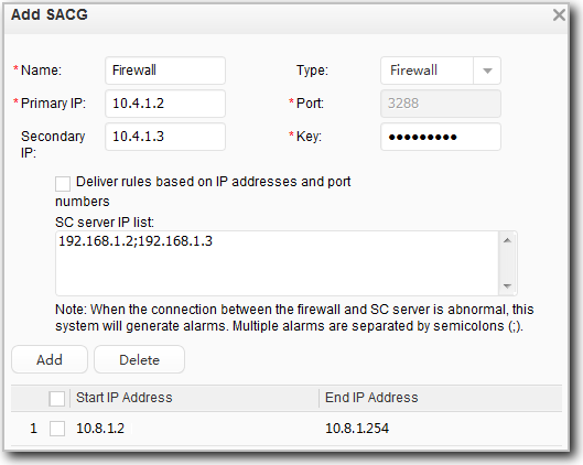
If NAT is configured to implement address translation between end users and the SC, set the IP address range (Start IP Address and End IP Address) to the range of translated IP addresses for end users but not the real IP addresses of terminals. Otherwise, end users cannot go online on the SACG.
- Configure the pre-authentication domain, isolation domain, and post-authentication domain.
- Click Add on the Pre-Authentication Domain tab.
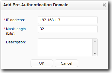
Add the IP addresses of the other servers in the pre-authentication to the pre-authentication domain.
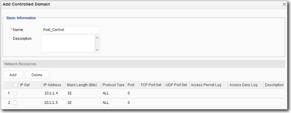
- Click Add on the Controlled Domain tab to add the isolation domain resources to a protected domain.
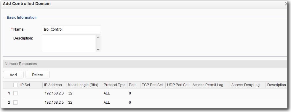
Repeat the preceding step to add the post-authentication resources to the protected domain.
- Click Add on the Isolation Domain tab to set the resource that end users can access.
- Click Add on the Post-Authentication Domain tab to set the post-authentication resource that end users can access only in working hours, that is the post_work resource.
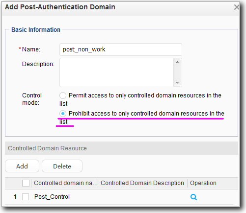
Add the resource that end users cannot access in non-working hours to the post-authentication domain according to the preceding steps.
- Click Add on the Pre-Authentication Domain tab.
- Configure and apply an SACG policy group to an account/user group or IP address segment.
- Configure a time segment to allow employees to access the service system only in working hours.
- Choose .
- Click Add.
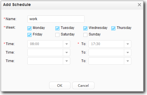
- Click OK.
- Configure an SACG policy group.
- Choose .
- Click Add.
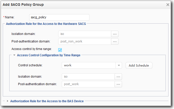
- Click OK.
- Apply the SACG policy group to an account/user group or IP address segment. In this example, the SACG policy group is applied to a user group.
The SACG policy group is applied to an account, user group, and IP address segment in descending order of matched priorities.
Click
 next to SACG policy to apply the SACG policy to the specified user group.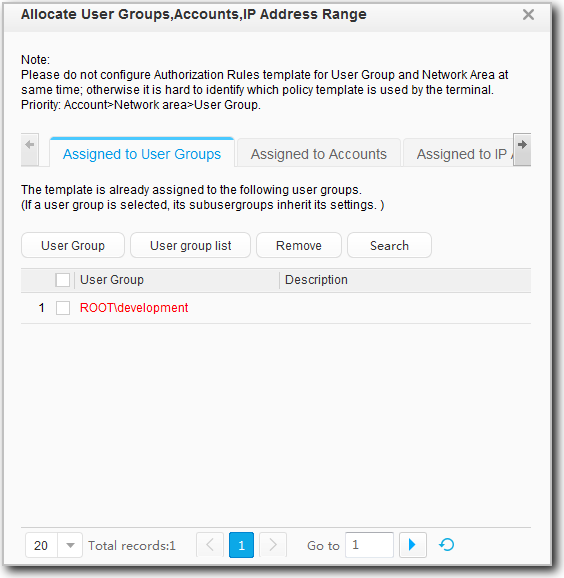
- Configure a time segment to allow employees to access the service system only in working hours.
- Configure the firewall to function as the hardware SACG.
Verification
- If a user successfully passes authentication and terminal security check, the user can access the service system in working hours but not in non-working hours.
- If a severe violation occurs, the terminal host cannot access a network and a message is displayed indicating that repair is required. The terminal host can access to the network after the repair.
- View the state of the Service Controller.
# View the state of the Service Controller on the active FW.
HRP_M<FW-3> display right-manager server-group
 Server group state  :  Enable
 Server number :     2
 Server ip address        Port        State       Master
 192.168.1.2              3288        active        Y
 192.168.1.3              3288        active        N
active indicates that the status of the connection between the Agile Controller and FW is normal.
# View the state of the Service Controller on the standby FW.
HRP_S<FW-4> display right-manager server-group
 Server group state  :  Enable
 Server number :     2
 Server ip address        Port        State       Master
 192.168.1.2              3288        active        Y
 192.168.1.3              3288        active        N
After the branch user logs in, you can view the user login information on both FWs. The following part shows the display right-manager online-users command output on the active FW.
HRP_M<FW-3> display right-manager online-users
  User name    : lee
  Ip address   : 10.8.1.3
  ServerIp     : 192.168.1.2
  Login time   : 10:14:11 2016/05/06 ( Hour:Minute:Second Year/Month/Day)
-----------------------------------------
  Role id      Rolename
     1          DefaultDeny
     6          Permit_1
   255          Last
-----------------------------------------
Run the display right-manager role-info command to view the mappings between roles and ACLs.
HRP_M<FW-3> display right-manager role-info
 All Role count:8
 Role  ID      ACL number      Role name
------------------------------------------------------------------------------
 Role   0      3099            default
 Role   1      3100            DefaultDeny
 Role   2      3101            DefaultPermit
 Role   3      3102            Deny___0
 Role   4      3103            Permit_0
------------------------------------------------------------------------------
 Role   5      3104            Deny___1
 Role   6      3105            Permit_1
 Role 255      3354            Last
Run the display acl acl-number command to view ACLs 3100, 3105, and 3354.
HRP_M<FW-3> display acl 3100
Advanced ACL  3100, 1 rule     //Default deny rule, used when Control mode in the isolation and post-authentication domains is selected as Permits                                 access to only controlled domain resources in the list.
Acl's step is 1

Acl's step is 1
 rule 1 deny ip (0 times matched)
HRP_M<FW-3> display acl 3105
Advanced ACL  3105, 1 rule     //Permit the access to the post-authentication domain.
Acl's step is 1
 rule 1 permit ip destination 10.1.1.4 0 (0 times matched)
 rule 2 permit ip destination 10.1.1.5 0 (0 times matched)
HRP_M<FW-3> display acl 3354
Advanced ACL  3354, 3 rules     //Permit the access to the pre-authentication domain.
Acl's step is 1
 rule 1 permit ip destination 192.168.1.2 0 (0 times matched)
 rule 2 permit ip destination 192.168.1.3 0 (0 times matched)
 rule 3 permit ip destination 192.168.3.3 0 (0 times matched)
From the previous information, account lee corresponds to roles 1, 6, and 255, and the matching sequence is from top to bottom. The role-ACL relationship indicates the ACL rules for the three roles.
Role 255 is allowed to access the pre-authentication domain, role 6 is allowed to access the service system, and role 1 is prohibited from accessing all services.
In conclusion, account lee is allowed to access only the pre-authentication domain and the service system in the post-authentication domain.
- Choose on the Agile Controller to check user login information.
Configuration Scripts
FW-3 |
FW-4 |
|---|---|
# hrp enable hrp interface GigabitEthernet 0/0/3 remote 10.10.10.2 # undo firewall session link-state check # interface GigabitEthernet 0/0/1 description SACG1_To_Coreswitch1_GE1/1/0/3 ip address 10.4.1.2 255.255.255.248 vrrp vrid 1 virtual-ip 10.4.1.1 active link-group 1 # interface GigabitEthernet 0/0/2 description SACG1_To_Coreswitch1_GE1/1/0/4 ip address 10.5.1.2 255.255.255.248 vrrp vrid 2 virtual-ip 10.5.1.1 active link-group 1 # interface GigabitEthernet 0/0/3 description hrp_interface ip address 10.10.10.1 255.255.255.0 # firewall zone trust add interface GigabitEthernet 0/0/1 # firewall zone untrust add interface GigabitEthernet 0/0/2 # firewall zone dmz add interface GigabitEthernet 0/0/3 # firewall interzone trust untrust apply packet-filter right-manager inbound # ip route-static 0.0.0.0 0.0.0.0 10.4.1.4 # firewall session aging-time service-set tcp_1414 40000 # right-manager server-group default acl 3099 server ip 192.168.1.2 port 3288 shared-key %$%$FxDAFSd(Y*Ku3%4+"%$%$ server ip 192.168.1.3 port 3288 shared-key %ef<f%7FxDAFSd(Y*Ku3%><dfe%&%$ integrity-check enable right-manager server-group enable right-manager status-detect enable local ip 10.4.1.2 right-manager authentication url http://192.168.1.2:8084/auth right-manager authentication url http://192.168.1.3:8084/auth # security-policy rule name sc_to_sacg source-zone trust source-zone local destination-zone local destination-zone trust action permit rule name sacg_to_client source-zone local destination-zone untrust action permit |
# hrp enable hrp interface GigabitEthernet 0/0/3 remote 10.10.10.1 # undo firewall session link-state check # interface GigabitEthernet 0/0/1 description SACG2_To_Coreswitch2_GE2/1/0/3 ip address 10.4.1.3 255.255.255.248 vrrp vrid 1 virtual-ip 10.4.1.1 standby link-group 1 # interface GigabitEthernet 0/0/2 description SACG2_To_Coreswitch2_GE2/1/0/4 ip address 10.5.1.3 255.255.255.248 vrrp vrid 2 virtual-ip 10.5.1.1 standby link-group 1 # interface GigabitEthernet 0/0/3 description hrp_interface ip address 10.10.10.2 255.255.255.0 # firewall zone trust add interface GigabitEthernet 0/0/1 # firewall zone untrust add interface GigabitEthernet 0/0/2 # firewall zone dmz add interface GigabitEthernet 0/0/3 # firewall interzone trust untrust apply packet-filter right-manager inbound # ip route-static 0.0.0.0 0.0.0.0 10.4.1.4 # firewall session aging-time service-set tcp_1414 40000 # right-manager server-group default acl 3099 server ip 192.168.1.2 port 3288 shared-key %$%$FxDAFSd(Y*Ku3%4+"%$%$ server ip 192.168.1.3 port 3288 shared-key %ef<f%7FxDAFSd(Y*Ku3%><dfe%&%$ integrity-check enable right-manager server-group enable right-manager status-detect enable local ip 10.4.1.3 right-manager authentication url http://192.168.1.2:8084/auth right-manager authentication url http://192.168.1.3:8084/auth # security-policy rule name sc_to_sacg source-zone trust source-zone local destination-zone local destination-zone trust action permit rule name sacg_to_client source-zone local destination-zone untrust action permit |