Web: Example for Configuring a Static Route-based GRE Tunnel
This section provides an example for configuring a GRE tunnel to which two devices direct traffic based on static routes.
Networking Requirements
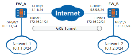
As shown in Figure 1, FW_A and FW_B are connected over the Internet and have reachable public routes to each other. Networks 1 and 2 are private IP networks. A GRE tunnel is required between the FWs to interconnect the two private IP networks.
Data Planning
Item |
Data |
Description |
|---|---|---|
FW_A |
Interface configuration |
Interface: GigabitEthernet 0/0/1 IP address: 1.1.1.1/24 Security zone: Untrust |
Interface: GigabitEthernet 0/0/2 IP address: 10.1.1.1/24 Security zone: Trust |
||
GRE configuration |
Interface name: Tunnel IP address: 172.16.2.1/24 Source address: 1.1.1.1/24 Destination address: 5.5.5.5/24 GRE Key:123456 |
|
FW_B |
Interface configuration |
Interface: GigabitEthernet 0/0/1 IP address: 5.5.5.5/24 Security zone: Untrust |
Interface: GigabitEthernet 0/0/2 IP address: 10.1.2.1/24 Security zone: Trust |
||
GRE configuration |
Interface name: Tunnel IP address: 172.16.2.2/24 Source address: 5.5.5.5/24 Destination address: 1.1.1.1/24 GRE Key:123456 |
Configuration Roadmap
- Create a tunnel interface on FW_A and FW_B respectively.
Set encapsulation parameters on the tunnel interface, such as the source and destination IP addresses of the tunnel.
- On FW_A and FW_B, configure a static route and specify the local tunnel interface as the outbound interface of the route.
The route directs traffic to be transmitted over the GRE tunnel to the GRE tunnel.
- Configure security policies to allow GRE tunnel setup and traffic forwarding.
Procedure
- Configure FW_A.
Configure IP addresses for interfaces and assign the interfaces to security zones.
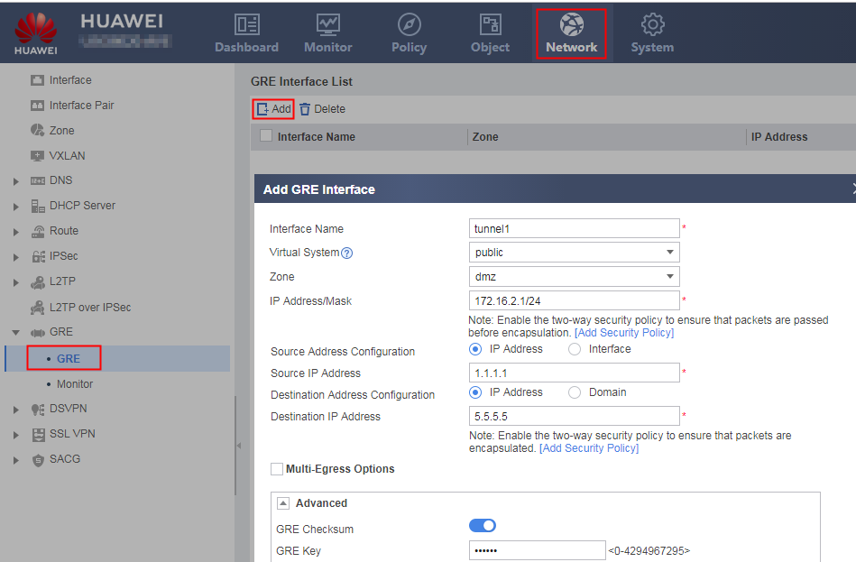
Configure encapsulation parameters for the tunnel interface.
Configure a static route to direct traffic to be transmitted over the GRE tunnel to the GRE tunnel.
- Choose .
- Click Add and set parameters as follows.
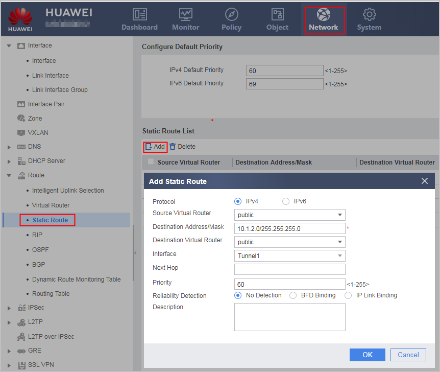
Protocol
IPv4
Destination Address/Mask
10.1.2.0/255.255.255.0
Interface
Tunnel1
Configure interzone security policies.
Configure a Trust-DMZ interzone security policy to permit pre-encapsulated packets.
Click Add. On the page that is displayed, select Add Security and set the following parameters.
Name
policy1
Source Zone
trust
Destination Zone
dmz
Action
Permit
- Click OK.
- Repeat the preceding steps to configure a DMZ -> Trust interzone policy.
Name
policy2
Source Zone
dmz
Destination Zone
trust
Action
Permit
Repeat the preceding steps to configure a Local -> Untrust interzone security policy to permit encapsulated GRE packets.
Name
policy3
Source Zone
local
Destination Zone
untrust
Action
Permit
Repeat the preceding steps to configure an Untrust -> Local interzone security policy to permit encapsulated GRE packets.
Name
policy4
Source Zone
untrust
Destination Zone
local
Action
Permit
- Configure FW_B.
Configure IP addresses for interfaces and assign the interfaces to security zones.
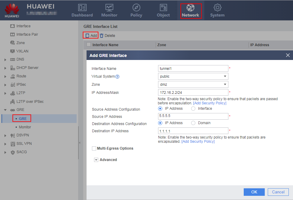
Configure encapsulation parameters for the tunnel interface.
Configure a static route to direct traffic to be transmitted over the GRE tunnel to the GRE tunnel.
- Choose .
- Click Add and set parameters as follows.
Protocol
IPv4
Destination Address/Mask
10.1.1.0/255.255.255.0
Interface
Tunnel1
Configure interzone security policies.
Configure a Trust-DMZ interzone security policy to permit pre-encapsulated packets.
Click Add. On the page that is displayed, select Add Security and set the following parameters.
Name
policy1
Source Zone
trust
Destination Zone
dmz
Action
Permit
- Click OK.
- Repeat the preceding steps to configure a DMZ -> Trust interzone policy.
Name
policy2
Source Zone
dmz
Destination Zone
trust
Action
Permit
Repeat the preceding steps to configure a Local -> Untrust interzone security policy to permit encapsulated GRE packets.
Name
policy3
Source Zone
local
Destination Zone
untrust
Action
Permit
Repeat the preceding steps to configure an Untrust -> Local interzone security policy to permit encapsulated GRE packets.
Name
policy4
Source Zone
untrust
Destination Zone
local
Action
Permit

Verification
- PCs on networks 1 and 2 can ping each other.
- On FW_A, choose . The route whose destination IP address is 10.1.2.0/24 and outbound interface is Tunnel1 is available.
Configuration Scripts
-
#
 sysname FW_A
#
interface GigabitEthernet0/0/1
 ip address 1.1.1.1 255.255.255.0
#
interface GigabitEthernet0/0/2
 ip address 10.1.1.1 255.255.255.0
#
interface Tunnel1
 ip address 172.16.2.1 255.255.255.0
 tunnel-protocol gre
 source 1.1.1.1
 destination 5.5.5.5
 gre key cipher %^%#=F~T>w'>n:QlQ8BI3>67Ir3I*Onzv'\(%^%#
 alias tunnel 1
 keepalive
#
ip route-static 10.1.2.0 255.255.255.0 Tunnel1
#
firewall zone trust
 set priority 85
 add interface GigabitEthernet0/0/2
#
firewall zone untrust
 set priority 5
 add interface GigabitEthernet0/0/1
#
firewall zone dmz
 set priority 50
 add interface Tunnel 1
#
security-policy
 rule name policy1
  source-zone trust
  destination-zone dmz
  action permit
 rule name policy2
  source-zone dmz
  destination-zone trust
  action permit
 rule name policy3
  source-zone local
  destination-zone untrust
  service gre
  action permit
 rule name policy4
  source-zone untrust
  destination-zone local
  service gre
  action permit
#
return
-
#
 sysname FW_B
#
interface GigabitEthernet0/0/1
 ip address 5.5.5.5 255.255.255.0
#
interface GigabitEthernet0/0/2
 ip address 10.1.2.1 255.255.255.0
#
interface Tunnel1
 ip address 172.16.2.2 255.255.255.0
 tunnel-protocol gre
 source 5.5.5.5
 destination 1.1.1.1
 gre key cipher %^%#=F~T>w'>n:QlQ8BI3>67Ir3I*Onzv'\(%^%#
 alias tunnel 1
 keepalive
#
ip route-static 10.1.1.0 255.255.255.0 Tunnel1
#
firewall zone trust
 set priority 85
 add interface GigabitEthernet0/0/2
#
firewall zone untrust
 set priority 5
 add interface GigabitEthernet0/0/1
#
firewall zone dmz
 set priority 50
 add interface Tunnel 1
#
security-policy
 rule name policy1
  source-zone trust
  destination-zone dmz
  action permit
 rule name policy2
  source-zone dmz
  destination-zone trust
  action permit
 rule name policy3
  source-zone local
  destination-zone untrust
  service gre
  action permit
 rule name policy4
  source-zone untrust
  destination-zone local
  service gre
  action permit
#
return