Web: Example for Configuring an OSPF-based GRE Tunnel
This section provides an example for configuring GRE tunnel to enable two connected private IP networks to exchange OSPF routing information over the Internet.
Networking Requirements
As shown in Figure 1, FW_A and FW_B are connected over the Internet and have reachable public routes to each other. Networks 1 and 2 are private IP networks and run OSPF. A GRE tunnel needs to be established between the FWs to enable their connected two private IP networks to exchange OSPF routing information over the Internet.
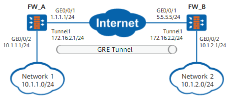
Configuration Roadmap
- Create a tunnel interface on FW_A and FW_B respectively.
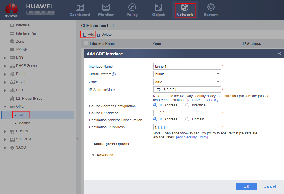
Set encapsulation parameters on the tunnel interface, such as the source and destination IP addresses of the tunnel.
- Configuring OSPF.
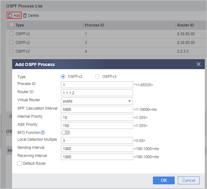
Enable an OSPF process and specify OSPF-capable interfaces. In this example, network segment 10.1.1.0/24 of network 1 and network segment 172.16.2.0/24 where the tunnel interface resides are advertised to network 2 through the GRE tunnel. The tunnel interfaces establish an OSPF adjacency over the GRE tunnel.
- Configure security policies to allow GRE tunnel setup and traffic forwarding.
Data Planning
Item |
Data |
Description |
|---|---|---|
FW_A |
Interface configuration |
Interface: GigabitEthernet 0/0/1 IP address: 1.1.1.1/24 Security zone: Untrust |
Interface: GigabitEthernet 0/0/2 IP address: 10.1.1.1/24 Security zone: Trust |
||
GRE configuration |
Interface name: Tunnel IP address: 172.16.2.1/24 Source address: 1.1.1.1/24 Destination address: 5.5.5.5/24 GRE Key:123456 |
|
FW_B |
Interface configuration |
Interface: GigabitEthernet 0/0/1 IP address: 5.5.5.5/24 Security zone: Untrust |
Interface: GigabitEthernet 0/0/2 IP address: 10.1.2.1/24 Security zone: Trust |
||
GRE configuration |
Interface name: Tunnel IP address: 172.16.2.2/24 Source address: 5.5.5.5/24 Destination address: 1.1.1.1/24 GRE Key:123456 |
Procedure
- Configure FW_A.
- Configure IP addresses for interfaces and assign the interfaces to security zones.
- Configure OSPF routes.
- Configure encapsulation parameters for the tunnel interface.
- Configure interzone security policies.Configure a Trust-DMZ interzone security policy to permit pre-encapsulated packets.
Click Add. On the page that is displayed, select Add Security and set the following parameters.
Name
policy1
Source Zone
trust
Destination Zone
dmz
Action
Permit
- Click OK.
- Repeat the preceding steps to configure a DMZ -> Trust interzone policy.
Name
policy2
Source Zone
dmz
Destination Zone
trust
Action
Permit
Repeat the preceding steps to configure a Local -> Untrust interzone security policy to permit encapsulated GRE packets.Name
policy3
Source Zone
local
Destination Zone
untrust
Action
Permit
Repeat the preceding steps to configure a Untrust -> Local interzone security policy to permit encapsulated GRE packets.Name
policy4
Source Zone
untrust
Destination Zone
local
Action
Permit
- Configure FW_B.
- Configure IP addresses for interfaces and assign the interfaces to security zones.
- Configure OSPF routes.
- Configure encapsulation parameters for the tunnel interface.
- Configure interzone security policies.Configure a Trust-DMZ interzone security policy to permit pre-encapsulated packets.
Click Add. On the page that is displayed, select Add Security and set the following parameters.
Name
policy1
Source Zone
trust
Destination Zone
dmz
Action
Permit
- Click OK.
- Repeat the preceding steps to configure a DMZ -> Trust interzone policy.
Name
policy2
Source Zone
dmz
Destination Zone
trust
Action
Permit
Repeat the preceding steps to configure a Local -> Untrust interzone security policy to permit encapsulated GRE packets.Name
policy3
Source Zone
local
Destination Zone
untrust
Action
Permit
Repeat the preceding steps to configure a Untrust -> Local interzone security policy to permit encapsulated GRE packets.Name
policy4
Source Zone
untrust
Destination Zone
local
Action
Permit

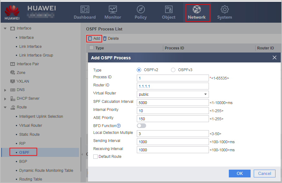

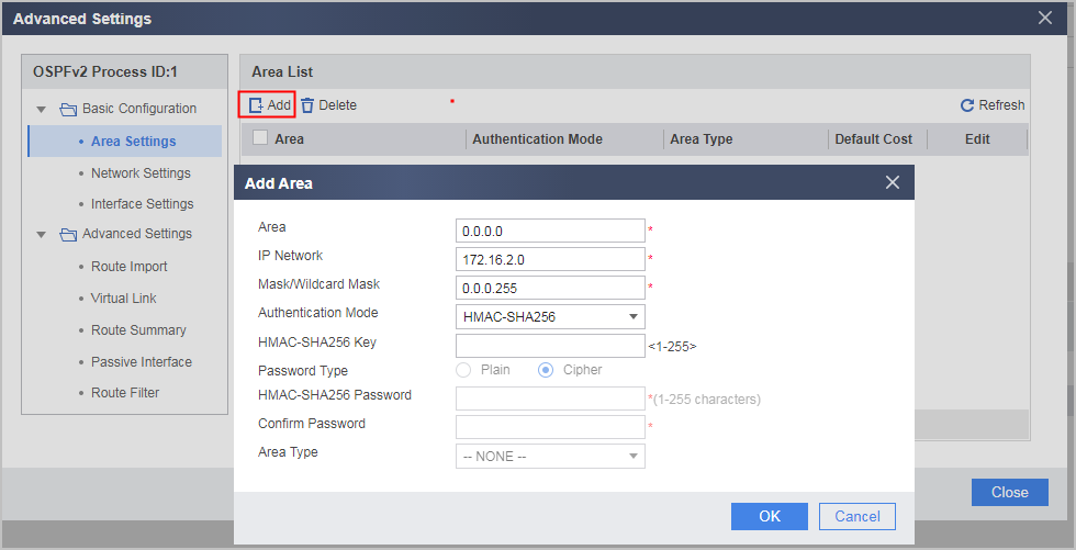
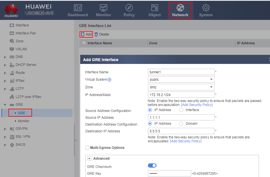
Verification
- PCs on networks 1 and 2 can ping each other.
- On FW_A, choose . The route whose destination IP address is 10.1.2.0/24 and outbound interface is Tunnel1 is available.
Configuration Scripts
-
#
 sysname FW_A
#
interface GigabitEthernet0/0/1
 ip address 1.1.1.1 255.255.255.0
#
interface GigabitEthernet0/0/2
 ip address 10.1.1.1 255.255.255.0
#
interface Tunnel1
 ip address 172.16.2.1 255.255.255.0
 tunnel-protocol gre
 source 1.1.1.1
 destination 5.5.5.5
 gre key cipher %^%#=F~&KLI;T>w'>n:QlQ8BI3>67Ir3I*Onzv'\&ii(%^%#
 alias tunnel 1
 keepalive
#
ospf 1
 area 0.0.0.0
  network 10.1.1.0 0.0.0.255
  network 172.16.2.0 0.0.0.255
#
firewall zone trust
 set priority 85
 add interface GigabitEthernet0/0/2
#
firewall zone untrust
 set priority 5
 add interface GigabitEthernet0/0/1
#
firewall zone dmz
 set priority 50
 add interface Tunnel 1
#
security-policy
 rule name policy1
  source-zone trust
  destination-zone dmz
  action permit
 rule name policy2
  source-zone dmz
  destination-zone trust
  service gre
  action permit
 rule name policy3
  source-zone local
  destination-zone untrust
  service gre
  action permit
 rule name policy4
  source-zone untrust
  destination-zone local
  service gre
  action permit
#
return
-
#
 sysname FW_B
#
interface GigabitEthernet0/0/1
 ip address 5.5.5.5 255.255.255.0
#
interface GigabitEthernet0/0/2
 ip address 10.1.2.1 255.255.255.0
#
interface Tunnel1
 ip address 172.16.2.2 255.255.255.0
 tunnel-protocol gre
 source 5.5.5.5
 destination 1.1.1.1
 gre key cipher %^%#=F~&KLI;T>w'>n:QlQ8BI3>67Ir3I*Onzv'\&ii(%^%#
 alias tunnel 1
 keepalive
#
ospf 1
 area 0.0.0.0
  network 10.1.2.0 0.0.0.255
  network 172.16.2.0 0.0.0.255

#
firewall zone trust
 set priority 85
 add interface GigabitEthernet0/0/2
#
firewall zone untrust
 set priority 5
 add interface GigabitEthernet0/0/1
#
firewall zone dmz
 set priority 50
 add interface Tunnel 1
#
security-policy
 rule name policy1
  source-zone trust
  destination-zone dmz
  action permit
 rule name policy2
  source-zone dmz
  destination-zone trust
  service gre
  action permit
 rule name policy3
  source-zone local
  destination-zone untrust
  service gre
  action permit
 rule name policy4
  source-zone untrust
  destination-zone local
  service gre
  action permit
#
return