Web: Example for Configuring Gateways to Negotiate IPSec VPN Tunnels Using IKE (Certificate Authentication)
This section provides an example to describe how to configure gateways with fixed IP addresses to establish IPSec VPN tunnels using certificate authentication.
Networking Requirements
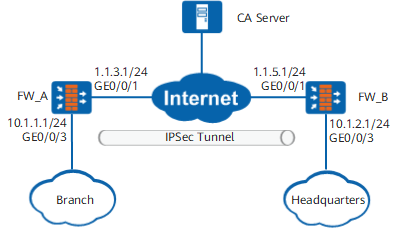
As shown in Figure 1, the enterprise branch and headquarters access the Internet through the FWs. To enhance communication security, the enterprise requires that an IPSec tunnel be established between the branch and headquarters using certificate authentication.
Data Planning
Item |
FW_A |
FW_B |
|---|---|---|
Interface configuration |
Interface number: GigabitEthernet 0/0/1 IP address: 1.1.3.1/24 Security zone: untrust |
Interface number: GigabitEthernet 0/0/1 IP address: 1.1.5.1/24 Security zone: untrust |
Interface number: GigabitEthernet 0/0/3 IP address: 10.1.1.1/24 Security zone: trust |
Interface number: GigabitEthernet 0/0/3 IP address: 10.1.2.1/24 Security zone: trust |
|
IPSec configuration |
Scenario: point-to-point Peer IP address: 1.1.5.1 Authentication method: RSA signature Local ID: IP address Peer ID: IP address |
Scenario: point-to-point Peer IP address: 1.1.3.1 Authentication method: RSA signature Local ID: IP address Peer ID: IP address |
Configuration Roadmap
The roadmaps for configuring FW_A and FW_B are the same:
- Set IP addresses for interfaces and add the interfaces to security zones.
- Configure security policies to allow specific subnets to communicate.
- Configure the default route.
- Configure FW_A and FW_B to apply for local and CA certificates in offline mode.
- Configure IPSec policies, including basic IPSec policy information, data flow to be protected by IPSec, and proposal parameters.
You need to import the local and CA certificates when configuring an IPSec policy.
Procedure
- Configure FW_A.
- Set interface IP addresses and assign the interfaces to security zones.
- Configure security policies to allow specific subnets to communicate.
Click Add and set the following parameters for the Trust -> Untrust interzone policy.
Name
policy_ipsec_1
Source Zone
trust
Destination Zone
untrust
Source Address/Region
10.1.1.0/24
Destination Address/Region
10.1.2.0/24
Action
Permit
- Click OK.
Repeat the preceding steps to configure Untrust -> Trust, Untrust -> Local, and Local -> Untrust interzone policies.
The parameters of the security policy for the Untrust -> Trust interzone are as follows.
Name
policy_ipsec_2
Source Zone
untrust
Destination Zone
trust
Source Address/Region
10.1.2.0/24
Destination Address/Region
10.1.1.0/24
Action
Permit
The parameters of the Untrust -> Local interzone policy are as follows.
Name
policy_ipsec_3
Source Zone
untrust
Destination Zone
local
Source Address/Region
1.1.5.1/32
Destination Address/Region
1.1.3.1/32
Action
Permit
The parameters of the Local -> Untrust interzone policy are as follows.
Name
policy_ipsec_4
Source Zone
local
Destination Zone
untrust
Source Address/Region
1.1.3.1/32
Destination Address/Region
1.1.5.1/32
Action
Permit

The local-untrust interzone policy controls whether IKE negotiation packets can pass through the FW. This policy can use the source and destination addresses, protocol, or port as the matching condition. In this example, the source and destination addresses are used as the matching condition. To use the protocol or port as the matching condition, you need to enable ESP and port 500 for UDP (port 4500 also in NAT traversal scenarios).
- Configure a default route. In the example, the next-hop IP address to the Internet is 1.1.3.2.
- Configure the IPSec tunnel on FW_A.
- Choose , click Add, and set the parameters shown in the following figure.
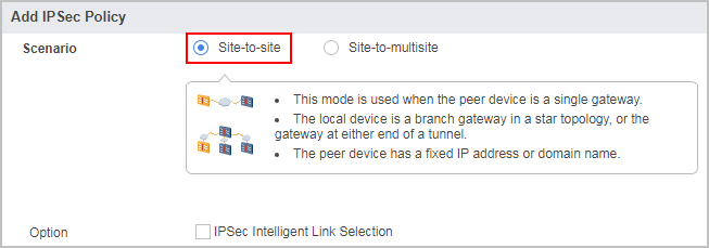
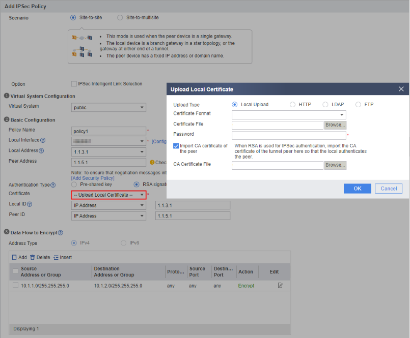
In the example, the default parameter settings are recommended for the IPSec proposal. To change parameter values, expand the Advanced settings of IKE/IPSec Proposal. The security proposals used by the tunnel ends must be the same.
When configuring certificate options, select Update Local Certificate from the certificate drop-down list.
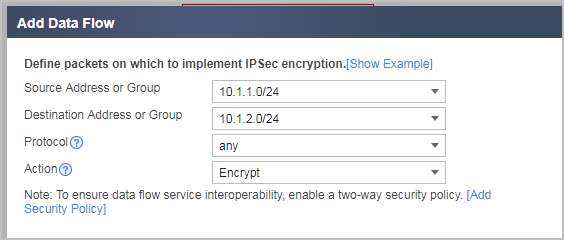
Configure one data flow to be encrypted. The parameter settings are provided in the following figure.
- Click Apply in the IPSec policy configuration to complete the configuration of FW_A.
- Choose , click Add, and set the parameters shown in the following figure.
- Configure FW_B.
- Set interface IP addresses and assign the interfaces to security zones.
- Configure security policies to allow specific subnets to communicate.
Click Add and set the following parameters for the Trust -> Untrust interzone policy.
Name
policy_ipsec_1
Source Zone
trust
Destination Zone
untrust
Source Address/Region
10.1.2.0/24
Destination Address/Region
10.1.1.0/24
Action
Permit
- Click OK.
Repeat the preceding steps to configure Untrust -> Trust, Untrust -> Local, and Local -> Untrust interzone policies.
The parameters of the security policy for the Untrust -> Trust interzone are as follows.
Name
policy_ipsec_2
Source Zone
untrust
Destination Zone
trust
Source Address/Region
10.1.1.0/24
Destination Address/Region
10.1.2.0/24
Action
Permit
The parameters of the Untrust -> Local interzone policy are as follows.
Name
policy_ipsec_3
Source Zone
untrust
Destination Zone
local
Source Address/Region
1.1.3.1/32
Destination Address/Region
1.1.5.1/32
Action
Permit
The parameters of the Local -> Untrust interzone policy are as follows.
Name
policy_ipsec_4
Source Zone
local
Destination Zone
untrust
Source Address/Region
1.1.5.1/32
Destination Address/Region
1.1.3.1/32
Action
Permit
The local-untrust interzone policy controls whether IKE negotiation packets can pass through the FW. This policy can use the source and destination addresses, protocol, or port as the matching condition. In this example, the source and destination addresses are used as the matching condition. To use the protocol or port as the matching condition, you need to enable ESP and port 500 for UDP (port 4500 also in NAT traversal scenarios).
- Configure the IPSec tunnel on FW_B.
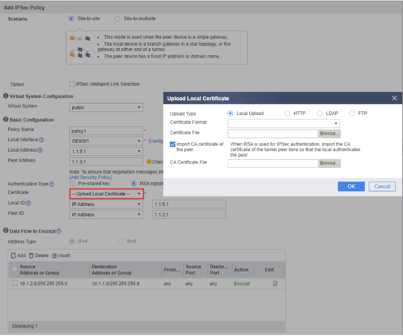
Choose , click Add, and set the parameters shown in the following figure.
In the example, the default parameter settings are recommended for the IPSec proposal. To change parameter values, expand the Advanced settings of IKE/IPSec Proposal. The security proposals used by the tunnel ends must be the same.
When configuring certificate options, select Update Local Certificate from the certificate drop-down list.
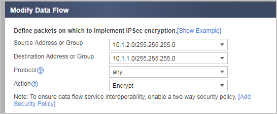
Configure one data flow to be encrypted. The parameter settings are provided in the following figure.
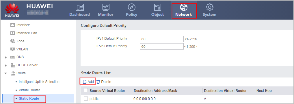
- Click Apply in the IPSec policy configuration to complete the configuration of FW_B.

Verification
Access a host or server on the headquarters network from a host on the branch network. The access succeeds.
On FW_A, choose to display the established tunnels. The following tunnel information is displayed:
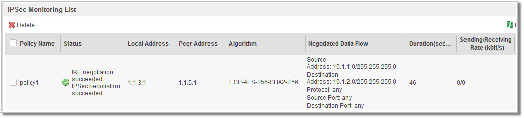
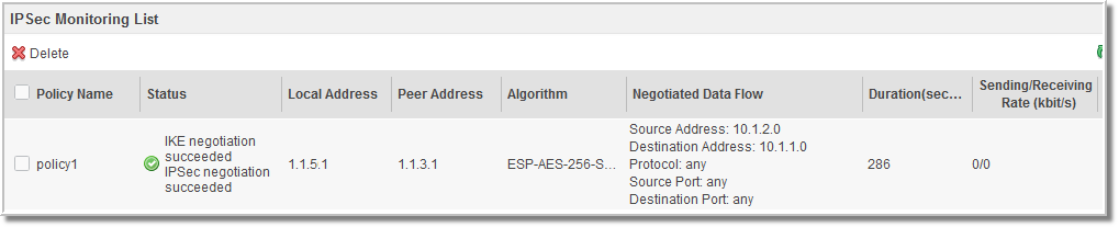
On FW_B, choose to display the established tunnels. The following tunnel information is displayed:
Configuration Scripts
-
#
acl number 3000
 rule permit ip source 10.1.1.0 0.0.0.255 destination 10.1.2.0 0.0.0.255
#
ike proposal 1
 encryption-algorithm aes-256
 dh group2
 authentication-algorithm sha2-256
 authentication-method rsa-signature
 integrity-algorithm hmac-sha2-256
 prf hmac-sha2-256
#
ike peer ike211154039363
 ike-proposal 1
 local-id-type fqdn
 local-id test.abc.com
 remote-address 1.1.2.1
 certificate local-filename fw_a.cer
#
ipsec proposal prop21115403936
 esp authentication-algorithm sha2-256
 esp encryption-algorithm aes-256
#
ipsec policy ipsec2111540396 1 isakmp
 security acl 3000
 ike-peer ike211154039363
 proposal prop21115403936
 tunnel local applied-interface
 alias policy1
 sa trigger-mode auto
#
interface GigabitEthernet0/0/3
 ip address 10.1.1.1 255.255.255.0
#
interface GigabitEthernet0/0/1
 ip address 1.1.3.1 255.255.255.0
 ipsec policy ipsec2111540396
#
firewall zone trust
 set priority 85
 add interface GigabitEthernet0/0/3
#
firewall zone untrust
 set priority 5
 add interface GigabitEthernet0/0/1
#
 ip route-static 0.0.0.0 0.0.0.0 1.1.3.2
#
security-policy
 rule name policy_ipsec_1
  source-zone trust
  destination-zone untrust
  source-address 10.1.1.0 mask 255.255.255.0
  destination-address 10.1.2.0 mask 255.255.255.0
  action permit
 rule name policy_ipsec_2
  source-zone untrust
  destination-zone trust
  source-address 10.1.2.0 mask 255.255.255.0
  destination-address 10.1.1.0 mask 255.255.255.0
  action permit
 rule name policy_ipsec_3
  source-zone untrust
  destination-zone local
  source-address 1.1.5.1 mask 255.255.255.255
  destination-address 1.1.3.1 mask 255.255.255.255
  action permit
 rule name policy_ipsec_4
  source-zone local
  destination-zone untrust
  source-address 1.1.3.1 mask 255.255.255.255
  destination-address 1.1.5.1 mask 255.255.255.255
  action permit
-
#
acl number 3000
 rule permit ip source 10.1.2.0 0.0.0.255 destination 10.1.1.0 0.0.0.255
#
ike proposal 1
 encryption-algorithm aes-256
 dh group2
 authentication-algorithm sha2-256
 authentication-method rsa-signature
 integrity-algorithm hmac-sha2-256
 prf hmac-sha2-256
#
ike peer ike41117138841
 ike-proposal 1
 local-id-type fqdn
 local-id test.abc.com
 remote-address 1.1.2.1
 certificate local-filename fw_b.cer
#
ipsec proposal prop2111540184
 esp authentication-algorithm sha2-256
 esp encryption-algorithm aes-256
#
ipsec policy ipsec2111540182 1 isakmp
 security acl 3000
 ike-peer ike41117138841
 proposal prop2111540184
 tunnel local applied-interface
 alias policy1
 sa trigger-mode auto
#
interface GigabitEthernet0/0/3
 ip address 10.1.2.1 255.255.255.0
#
interface GigabitEthernet0/0/1
 ip address 1.1.5.1 255.255.255.0
 ipsec policy ipsec2111540182
#
firewall zone trust
 set priority 85
 add interface GigabitEthernet0/0/3
#
firewall zone untrust
 set priority 5
 add interface GigabitEthernet0/0/1
#
 ip route-static 0.0.0.0 0.0.0.0 1.1.5.2
#
security-policy
 rule name policy_ipsec_1
  source-zone trust
  destination-zone untrust
  source-address 10.1.2.0 mask 255.255.255.0
  destination-address 10.1.1.0 mask 255.255.255.0
  action permit
 rule name policy_ipsec_2
  source-zone untrust
  destination-zone trust
  source-address 10.1.1.0 mask 255.255.255.0
  destination-address 10.1.2.0 mask 255.255.255.0
  action permit
 rule name policy_ipsec_3
  source-zone untrust
  destination-zone local
  source-address 1.1.3.1 mask 255.255.255.255
  destination-address 1.1.5.1 mask 255.255.255.255
  action permit
 rule name policy_ipsec_4
  source-zone local
  destination-zone untrust
  source-address 1.1.5.1 mask 255.255.255.255
  destination-address 1.1.3.1 mask 255.255.255.255
  action permit