Web: Example for Establishing IPSec VPN Tunnels Between the Headquarters and Multiple Branches
This section provides an example to describe how to enable the headquarters and branches to establish IPSec VPN tunnels in between.
Networking Requirements
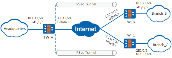
As shown in Figure 1, an enterprise has a headquarters and multiple branches, and the FWs are the egress gateways of the headquarters and branches. The headquarters egress gateway FW_A has a fixed IP address. The enterprise requires that IPSec VPN tunnels be established between the headquarters and branches for communication security.
Configuration Roadmap
The configuration roadmap is as follows:
Complete basic and routing configurations on interfaces and enable security policies.
-
Note that you do not need to set the peer IP address when configuring FW_A, because the peer IP address is not fixed. When you configure FW_B and FW_C, you need to set the peer IP address.
The roadmaps for configuring FW_A, FW_B, and FW_C are the same.
Data Planning
Item |
FW_A |
FW_B |
FW_C |
|---|---|---|---|
Interface configuration |
Interface number: GigabitEthernet 0/0/1 IP address: 1.1.3.1/24 Security zone: untrust Interface number: GigabitEthernet 0/0/3 IP address: 10.1.1.1/24 Security zone: trust |
Interface number: GigabitEthernet 0/0/1 IP address: 1.1.5.1/24 Security zone: untrust Interface number: GigabitEthernet 0/0/3 IP address: 10.1.2.1/24 Security zone: trust |
Interface number: GigabitEthernet 0/0/1 IP address: 1.1.6.1/24 Security zone: untrust Interface number: GigabitEthernet 0/0/3 IP address: 10.1.3.1/24 Security zone: trust |
IPSec configuration |
Scenario: point-to-multipoint Peer IP address: not configured Authentication mode: pre-shared key Pre-shared key: Test@123 Local ID: IP address Peer ID: any peer ID |
Scenario: point-to-point Peer IP address: 1.1.3.1 Authentication mode: pre-shared key Pre-shared key: Test@123 Local ID: IP address Peer ID: IP address |
Scenario: point-to-point Peer IP address: 1.1.3.1 Authentication mode: pre-shared key Pre-shared key: Test@123 Local ID: IP address Peer ID: IP address |
Procedure
- Configure FW_A (headquarters).
- Set interface IP addresses and assign the interfaces to security zones.
- Configure security policies to allow specific subnets to communicate.
Click Add and set the following parameters for the Trust -> Untrust interzone policy.
Name
policy_ipsec_1
Source Zone
trust
Destination Zone
untrust
Source Address/Region
10.1.1.0/24
Destination Address/Region
10.1.2.0/24
10.1.3.0/24
Action
Permit
- Click OK.
Repeat the preceding steps to configure Untrust -> Trust, Untrust -> Local, and Local -> Untrust interzone policies.
The parameters of the security policy for the Untrust -> Trust interzone are as follows.
Name
policy_ipsec_2
Source Zone
untrust
Destination Zone
trust
Source Address/Region
10.1.2.0/24
10.1.3.0/24
Destination Address/Region
10.1.1.0/24
Action
Permit
The parameters of the Untrust -> Local interzone policy are as follows.
Name
policy_ipsec_3
Source Zone
untrust
Destination Zone
local
Destination Address/Region
1.1.3.1/32
Action
Permit
The parameters of the Local -> Untrust interzone policy are as follows.
Name
policy_ipsec_4
Source Zone
local
Destination Zone
untrust
Source Address/Region
1.1.3.1/32
Action
Permit

The local-untrust interzone policy controls whether IKE negotiation packets can pass through the FW. This policy can use the source and destination addresses, protocol, or port as the matching condition. In this example, the source and destination addresses are used as the matching condition. To use the protocol or port as the matching condition, you need to enable ESP and port 500 for UDP (port 4500 also in NAT traversal scenarios).
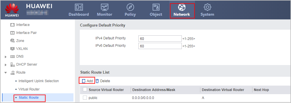
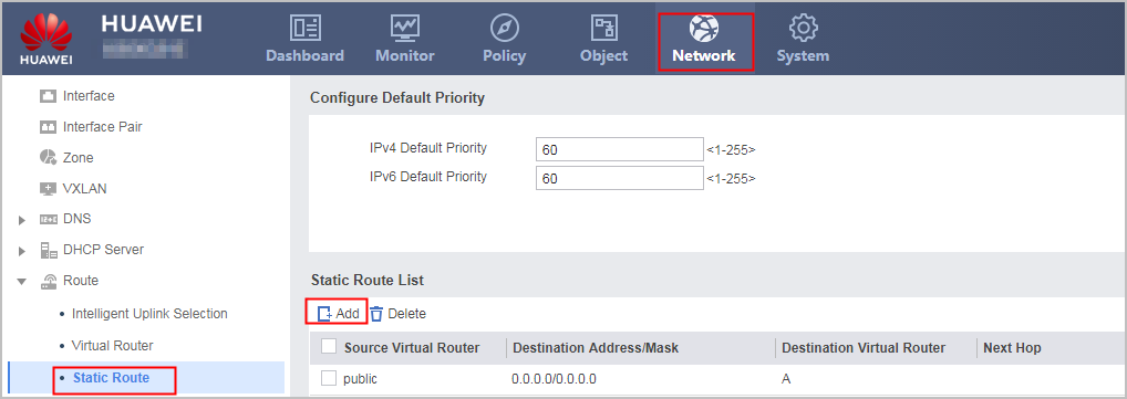
- Configure a default route. In the example, the next hop from FW_A to the Internet is 1.1.3.2.
- Configure an IPSec tunnel.
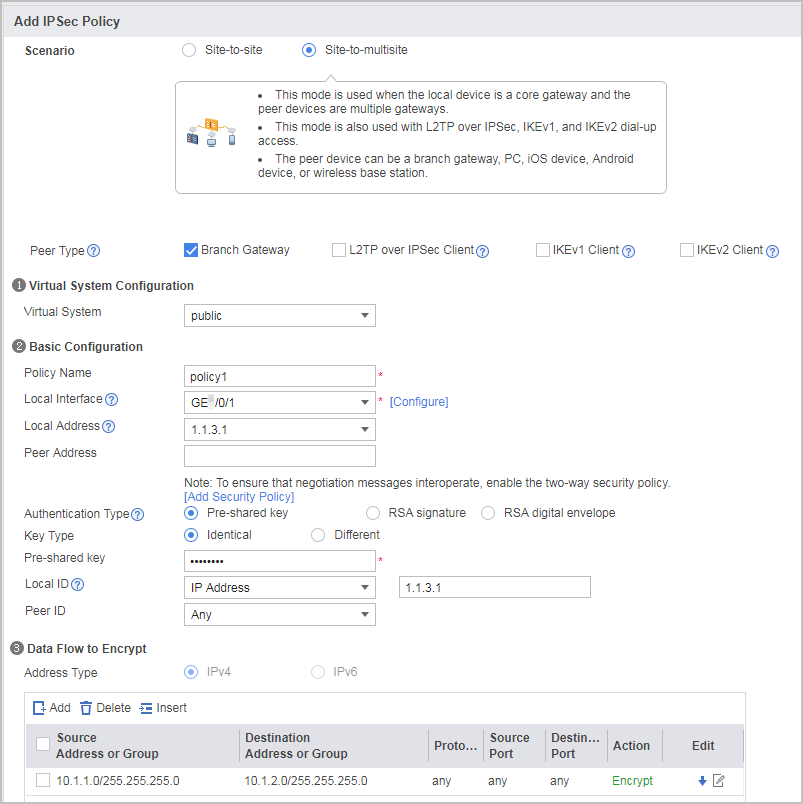
Choose , click Add, and set the parameters shown in the following figure.
In the example, the pre-shared key is Test@123, and the default parameters are used for the security proposal. To change parameter values, expand the advanced settings of the security proposal. The security proposals used by the tunnel ends must be the same.
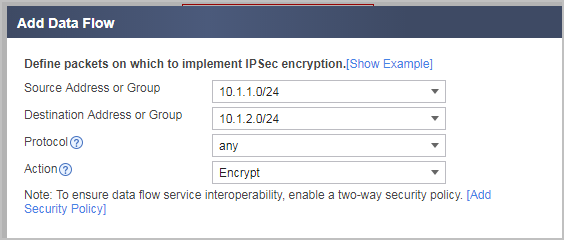
Configure two data flows to be encrypted. One data flow is used as an example for illustration. The parameter settings are provided in the following figure.
During packet forwarding, the IPSec module is behind the NAT module (NAT server, destination NAT, and source NAT). You need to ensure that the NAT server and destination NAT do not affect the processing of IPSec-protected data flow. The following requirements must be met:
Run the display firewall server-map command to check the source and destination IP addresses in the servermap table.
Ensure that the IPSec-protected data flow does not match the servermap table or reverse servermap table created on the NAT server. Otherwise, destination addresses of packets will be translated.
Run the display acl acl-number commands to check ACL information of the destination NAT policy.
Ensure that the IPSec-protected data flow does not match the destination NAT policy. Otherwise, destination addresses of packets will be translated.
Run the display current-configuration configuration policy-nat command to check source NAT policy information.
Ensure that the IPSec-protected data flow does not match the source NAT policy.
If NAT is required for the IPSec-protected data flow, the ACL needs to match the post-NAT IP address.
- Click Apply in the IPSec policy configuration to complete the configuration of FW_A.
- Configure FW_B (branch).
- Set interface IP addresses and assign the interfaces to security zones.
- Configure security policies to allow specific subnets to communicate.
Click Add and set the following parameters for the Trust -> Untrust interzone policy.
Name
policy_ipsec_1
Source Zone
trust
Destination Zone
untrust
Source Address/Region
10.1.2.0/24
Destination Address/Region
10.1.1.0/24
Action
Permit
- Click OK.
Repeat the preceding steps to configure Untrust -> Trust, Untrust -> Local, and Local -> Untrust interzone policies.
The parameters of the security policy for the Untrust -> Trust interzone are as follows.
Name
policy_ipsec_2
Source Zone
untrust
Destination Zone
trust
Source Address/Region
10.1.1.0/24
Destination Address/Region
10.1.2.0/24
Action
Permit
The parameters of the Untrust -> Local interzone policy are as follows.
Name
policy_ipsec_3
Source Zone
untrust
Destination Zone
local
Source Address/Region
1.1.3.1/32
Action
Permit
The parameters of the Local -> Untrust interzone policy are as follows.
Name
policy_ipsec_4
Source Zone
local
Destination Zone
untrust
Destination Address/Region
1.1.3.1/32
Action
Permit
The local-untrust interzone policy controls whether IKE negotiation packets can pass through the FW. This policy can use the source and destination addresses, protocol, or port as the matching condition. In this example, the source and destination addresses are used as the matching condition. To use the protocol or port as the matching condition, you need to enable ESP and port 500 for UDP (port 4500 also in NAT traversal scenarios).
- Configure a route to the peer end. In the example, the next-hop IP address from FW_B to the Internet is 1.1.5.2.
- Configure an IPSec tunnel.
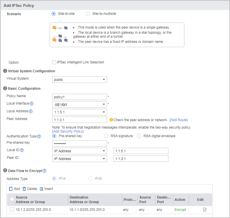
- Choose , click Add, and set the parameters shown in the following figure.
In the example, the pre-shared key is Test@123, and the default parameters are used for the security proposal. To change parameter values, expand the advanced settings of the security proposal. The security proposals used by the tunnel ends must be the same.
Configure one data flow to be encrypted. The parameter settings are provided in the following figure.
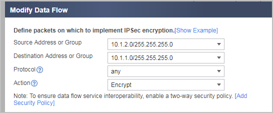
During packet forwarding, the IPSec module is behind the NAT module (NAT server, destination NAT, and source NAT). You need to ensure that the NAT server and destination NAT do not affect the processing of IPSec-protected data flow. The following requirements must be met:
Run the display firewall server-map command to check the source and destination IP addresses in the servermap table.
Ensure that the IPSec-protected data flow does not match the servermap table or reverse servermap table created on the NAT server. Otherwise, destination addresses of packets will be translated.
Run the display acl acl-number commands to check ACL information of the destination NAT policy.
Ensure that the IPSec-protected data flow does not match the destination NAT policy. Otherwise, destination addresses of packets will be translated.
Run the display current-configuration configuration policy-nat command to check source NAT policy information.
Ensure that the IPSec-protected data flow does not match the source NAT policy.
If NAT is required for the IPSec-protected data flow, the ACL needs to match the post-NAT IP address.
- Click Apply in the IPSec policy configuration to complete the configuration of FW_B.
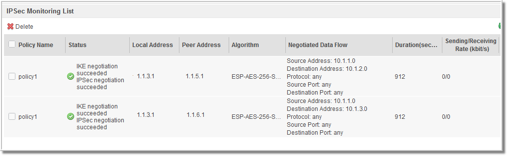
- Choose , click Add, and set the parameters shown in the following figure.
- Configure FW_C (branch).
Configure FW_C by referring to the configurations of FW_B.

Configuration Scripts
-
#
 acl number 3005
 rule 5 permit ip source 10.1.1.0 0.0.0.255 destination 10.1.2.0 0.0.0.255
 rule 10 permit ip source 10.1.1.0 0.0.0.255 destination 10.1.3.0 0.0.0.255
#
ike proposal 4
 encryption-algorithm aes-256
 dh group2
 authentication-algorithm sha2-256
 authentication-method pre-share
 integrity-algorithm hmac-sha2-256
 prf hmac-sha2-256
#
ike peer ike281142050612
 pre-shared-key %@%@"@^z$/|AD456.#D#gmH8W+GD%@%@
 ike-proposal 4
 local-id 1.1.3.1
#
ipsec proposal prop28114205061
 esp authentication-algorithm sha2-256
 esp encryption-algorithm aes-256
#
ipsec policy-template tpl281142050612 1
 security acl 3005
 ike-peer ike281142050612
 proposal prop28114205061
 alias policy1
#
ipsec policy ipsec2811420508 10000 isakmp template tpl281142050612
#
interface GigabitEthernet0/0/3
 ip address 10.1.1.1 255.255.255.0
#
interface GigabitEthernet0/0/1
 ip address 1.1.3.1 255.255.255.0
 ipsec policy ipsec2811420508
#
firewall zone trust
 set priority 85
 add interface GigabitEthernet0/0/3
#
firewall zone untrust
 set priority 5
 add interface GigabitEthernet0/0/1
#
ip route-static 0.0.0.0 0.0.0.0 1.1.3.2
#
security-policy
 rule name policy_ipsec_1
  source-zone trust
  destination-zone untrust
  source-address 10.1.1.0 mask 255.255.255.0
  destination-address 10.1.2.0 mask 255.255.255.0
  destination-address 10.1.3.0 mask 255.255.255.0
  action permit
 rule name policy_ipsec_2
  source-zone untrust
  destination-zone trust
  source-address 10.1.2.0 mask 255.255.255.0
  source-address 10.1.3.0 mask 255.255.255.0
  destination-address 10.1.1.0 mask 255.255.255.0
  action permit
 rule name policy_ipsec_3
  source-zone untrust
  destination-zone local
  destination-address 1.1.3.1 mask 255.255.255.255
  action permit
 rule name policy_ipsec_4
  source-zone local
  destination-zone untrust
  source-address 1.1.3.1 mask 255.255.255.255
  action permit
-
#
acl number 3000
 rule 5 permit ip source 10.1.2.0 0.0.0.255 destination 10.1.1.0 0.0.0.255
#
ike proposal 1
 encryption-algorithm aes-256
 dh group2
 authentication-algorithm sha2-256
 authentication-method pre-share
 integrity-algorithm hmac-sha2-256
 prf hmac-sha2-256
#
ike peer ike281142213393
 pre-shared-key %@%@X3c2!T#j2$U2^/)2:^65tK]X%@%@
 ike-proposal 1
 remote-id-type ip
 remote-id 1.1.3.1
 local-id 1.1.5.1
 remote-address 1.1.3.1
#
ipsec proposal prop28114221339
 esp authentication-algorithm sha2-256
 esp encryption-algorithm aes-256
#
ipsec policy ipsec2811422136 1 isakmp
 security acl 3000
 ike-peer ike281142213393
 proposal prop28114221339
 tunnel local applied-interface
 alias policy1
 sa trigger-mode auto
#
interface GigabitEthernet0/0/3
 ip address 10.1.2.1 255.255.255.0
#
interface GigabitEthernet0/0/1
 ip address 1.1.5.1 255.255.255.0
 ipsec policy ipsec2811422136
#
firewall zone trust
 set priority 85
 add interface GigabitEthernet0/0/3
#
firewall zone untrust
 set priority 5
 add interface GigabitEthernet0/0/1
#
ip route-static 0.0.0.0 0.0.0.0 1.1.5.2
#
security-policy
 rule name policy_ipsec_1
  source-zone trust
  destination-zone untrust
  source-address 10.1.2.0 mask 255.255.255.0
  destination-address 10.1.1.0 mask 255.255.255.0
   action permit
 rule name policy_ipsec_2
  source-zone untrust
  destination-zone trust
  source-address 10.1.1.0 mask 255.255.255.0
  destination-address 10.1.2.0 mask 255.255.255.0
  action permit
 rule name policy_ipsec_3
  source-zone untrust
  destination-zone local
  destination-address 1.1.5.1 mask 255.255.255.255
  action permit
 rule name policy_ipsec_4
  source-zone local
  destination-zone untrust
  source-address 1.1.5.1 mask 255.255.255.255
  action permit
-
#
acl number 3000
 rule 5 permit ip source 10.1.3.0 0.0.0.255 destination 10.1.1.0 0.0.0.255
#
ike proposal 1
 encryption-algorithm aes-256
 dh group2
 authentication-algorithm sha2-256
 authentication-method pre-share
 integrity-algorithm hmac-sha2-256
 prf hmac-sha2-256
#
ike peer ike281142213393
 pre-shared-key %@%@X3c2!T#j2$U2^/)2:^65tK]X%@%@
 ike-proposal 1
 remote-id-type ip
 remote-id 1.1.3.1
 local-id 1.1.6.1
 remote-address 1.1.3.1
#
ipsec proposal prop28114221339
 esp authentication-algorithm sha2-256
 esp encryption-algorithm aes-256
#
ipsec policy ipsec2811422136 1 isakmp
 security acl 3000
 ike-peer ike281142213393
 proposal prop28114221339
 tunnel local applied-interface
 alias policy1
 sa trigger-mode auto
#
interface GigabitEthernet0/0/3
 ip address 10.1.3.1 255.255.255.0
#
interface GigabitEthernet0/0/1
 ip address 1.1.6.1 255.255.255.0
 ipsec policy ipsec2811422136
#
firewall zone trust
 set priority 85
 add interface GigabitEthernet0/0/3
#
firewall zone untrust
 set priority 5
 add interface GigabitEthernet0/0/1
#
ip route-static 0.0.0.0 0.0.0.0 1.1.6.2
#
security-policy
 rule name policy_ipsec_1
  source-zone trust
  destination-zone untrust
  source-address 10.1.3.0 mask 255.255.255.0
  destination-address 10.1.1.0 mask 255.255.255.0
   action permit
 rule name policy_ipsec_2
  source-zone untrust
  destination-zone trust
  source-address 10.1.1.0 mask 255.255.255.0
  destination-address 10.1.3.0 mask 255.255.255.0
  action permit
 rule name policy_ipsec_3
  source-zone untrust
  destination-zone local
  destination-address 1.1.6.1 mask 255.255.255.255
  action permit
 rule name policy_ipsec_4
  source-zone local
  destination-zone untrust
  source-address 1.1.6.1 mask 255.255.255.255
  action permit