Web: Example for Configuring IPSec Intelligent Link Selection(Link switchover based on the link quality probe result)
As the gateway of a branch, the FW uses the IPSec intelligent link selection function for dynamic IPSec tunnel switching.
Networking Requirements
As shown in Figure 1, the headquarters and branch connect to the Internet through FW_A and FW_B, respectively. FW_A connects to the Internet through one link. FW_B connects to the Internet through two links.
The purposes of this networking are as follows:
- An IPSec tunnel is established between FW_A and FW_B for the communication between the headquarters and branch.
- FW_B first uses Link 1 to establish an IPSec tunnel to the headquarters. If the IPSec tunnel has a high packet loss ratio or delay, FW_B automatically uses Link 2 to establish another IPSec tunnel.
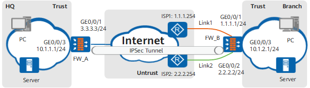

The local interface in IPSec intelligent link selection can be an interface that dynamically obtains IP addresses through PPPoE or DHCP. That is, when GE0/0/1 or GE0/0/2 on FW_B in Figure 1 obtains IP addresses through PPPoE or DHCP, the IPSec intelligent link selection function is also available.
The method for configuring IPSec intelligent link selection when the local interface has a fixed IP address is the same as that when the local interface obtains IP addresses dynamically.
Data Planning
Item |
Data |
|---|---|
FW_A |
Interface: GigabitEthernet 0/0/3 IP address: 10.1.1.1/24 Security zone: Trust |
Interface: GigabitEthernet 0/0/1 IP address: 3.3.3.3/24 Security zone: Untrust |
|
IPSec configuration Scenario: Site-to-multisite Peer IP Address: Do not Specify Peer Gateway Authentication Type: Pre-Shared Key Pre-Shared Key: Admin@123 Local ID: IP Address Peer ID: Any |
|
FW_B |
Interface: GigabitEthernet 0/0/1 IP address: 1.1.1.1/24 Security zone: Untrust |
Interface: GigabitEthernet 0/0/2 IP address: 2.2.2.2/24 Security zone: Untrust |
|
Interface: GigabitEthernet 0/0/3 IP address: 10.1.2.1/24 Security zone: Trust |
|
IPSec configuration Enable IPSec smart-link Scenario: Site-to-site Peer IP Address: 3.3.3.3 Authentication Type: Pre-Shared Key Pre-Shared Key: Admin@123 Local ID: IP Address Peer ID: Any |
|
Tunnel detection Switching times: 3 Detection packets: 10 Sending interval: 1s Source address of detection packets: IP address of the local IPSec tunnel interface; destination address of detection packets: IP address of the peer IPSec tunnel interface Packet loss ratio < 30% Delay < 500ms |
Procedure
- Configure FW_B (Branch).
- Set an IP address for each interface and assign the interfaces to security zones.
- Choose .
Click
 of GE0/0/1> and set the following parameters:
Zone
untrust
IPv4
IP Address
1.1.1.1/24
Default Gateway
1.1.1.254
- Click OK.
Repeat the preceding steps to set the parameters of the GE0/0/2 interface.
Zone
untrust
IPv4
IP Address
2.2.2.2/24
Default Gateway
2.2.2.254
Repeat the preceding steps to set the parameters of the GE0/0/3 interface.
Zone
trust
IPv4
IP Address
10.1.2.1/24
- Configure security policies to allow specific subnets to communicate.
Click Add and set the parameters of the security policy for the Trust->Untrust interzone as follows:
Name
policy_ipsec_1
Source Zone
trust
Destination Zone
untrust
Source Address/Region
10.1.2.0/24
Destination Address/Region
10.1.1.0/24
Action
Permit
- Click OK.
Repeat preceding steps to configure security policies for the Untrust -> Trust, Untrust -> Local, and Local -> Untrust interzones.
The parameters of the security policy for the Untrust -> Trust interzone are as follows:
Name
policy_ipsec_2
Source Zone
untrust
Destination Zone
trust
Source Address/Region
10.1.1.0/24
Destination Address/Region
10.1.2.0/24
Action
Permit
The parameters of the security policy for the Untrust -> Local interzone are as follows:
Name
policy_ipsec_3
Source Zone
untrust
Destination Zone
local
Source Address/Region
3.3.3.3/32
Destination Address/Region
1.1.1.1/32
2.2.2.2/32
Action
Permit
The parameters of the security policy for the Local -> Untrust interzone are as follows:
Name
policy_ipsec_4
Source Zone
local
Destination Zone
untrust
Source Address/Region
1.1.1.1/32
2.2.2.2/32
Destination Address/Region
3.3.3.3/32
Action
Permit
The local-untrust interzone policy controls whether IKE negotiation packets can pass through the FW. This policy can use the source and destination addresses, protocol, or port as the matching condition. In this example, the source and destination addresses are used as the matching condition. To use the protocol or port as the matching condition, you need to enable ESP and port 500 for UDP (port 4500 also in NAT traversal scenarios).
- Configure the IPSec tunnel on FW_B.
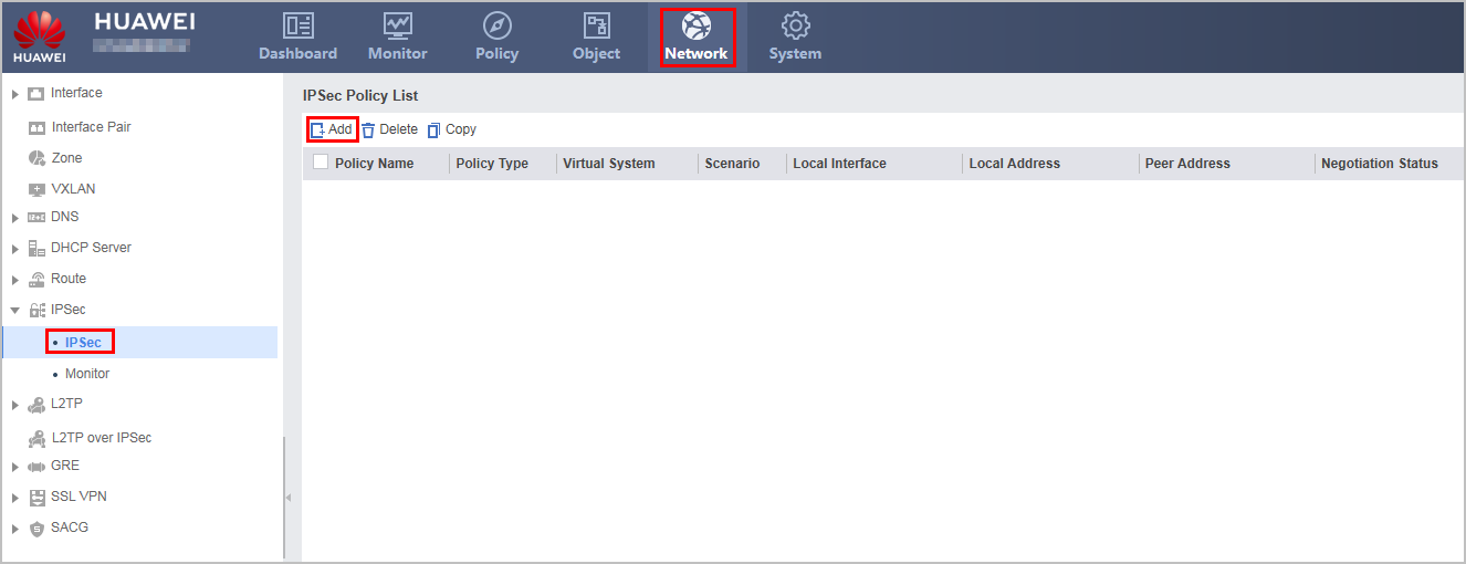
- Choose , click Add.
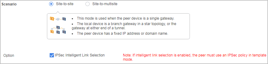
- Select Scenario as Site-to-site, and select IPSec Intelligent Link Selection.
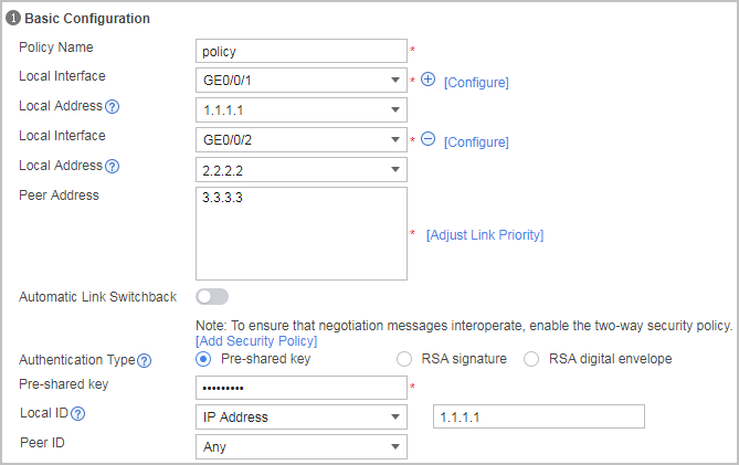
- Configure the basic IPSec policy information, specify the remote gateway, and set the pre-shared key to Admin@123.
The Automatic Link Switchback switch can be used to enable automatic switchback to a high-priority link. This function is disabled by default. After this function is enabled, you can set Switchback Delay.
After automatic switchback to a high-priority link in IPSec intelligent link selection is enabled, the FW continuously detects the quality (packet loss rate and delay) of the high-priority link after the IPSec tunnel is switched to the backup link. If the quality of the high-priority link continuously meets the requirements within the configured switchback delay, the FW automatically switches the IPSec tunnel back to the high-priority link.
After automatic switchback to a high-priority link is enabled, the tunnel detection parameters in the IPSec intelligent link selection rule on the local device and the data flows to be encrypted in the IPSec policy on the peer device are different in the following configurations compared with those before the automatic switchback function is enabled:
- The link detection addresses must be configured in the IPSec intelligent link selection rule on the local device (Step e). The source and destination IP addresses of the detection packets can not be the IP addresses of the interfaces at the two ends of the IPSec tunnel, they can be the IP addresses contained in the data flows to be encrypted.
- The IPSec policy of the peer device must be configured with to-be-encrypted data flows whose source IP address is the destination IP address of the destination packets, destination IP address is the source IP address of the detection packets, and protocol type is ICMP. For example, if the source IP address of the detection packets on the local device is 1.1.1.1 and the destination IP address is 2.2.2.2, then the source IP address of the data flows to be encrypted is 2.2.2.2, the destination IP address is 1.1.1.1, the protocol type is ICMP, and the action is Encrypt. In addition, the link detection addresses are configured on the local device and the FW does not use the IP addresses of the interfaces at the two ends of the link as the source address and destination address of the detection packets. Therefore, you do not need to configure to-be-encrypted data flows that use the IP addresses of the interfaces at the two ends of the IPSec tunnel as the source and destination IP addresses on the peer device.
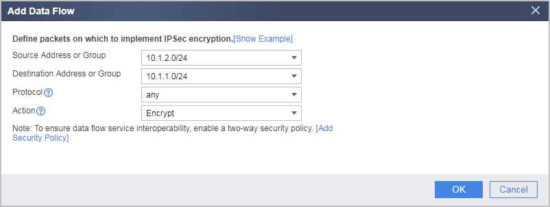
- Under Data Flow to Encrypt, click Add to add a data flow as follows.
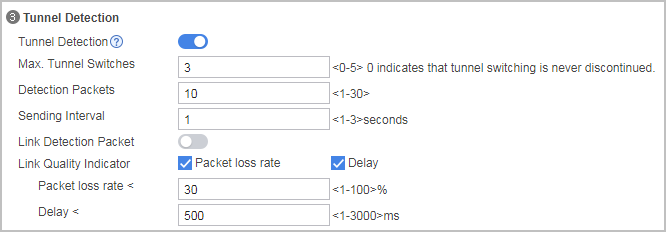
- Configure tunnel detection.
If Link Detection Packet is clear, FW_B uses the local and peer IPSec tunnel interface IP addresses as the source and destination IP addresses of detection packets respectively.
If Link Detection Packet is selected, you can specify source and destination IP addresses for detection packets.
- Under IKE/IPSec Proposal, expand Advanced, and configure IPSec proposal as follows.
In this example, all proposal parameters are set to default values, as shown in the following figure. If you change the value of a parameter, you must ensure that the parameter settings are the same on both tunnel ends.
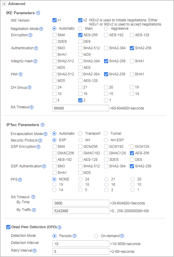
Click Apply. The configuration of FW_B is complete.
After the configuration is delivered, FW_B automatically adds a rule to Data Flow to Encrypt in the IPSec policy based on the source and destination IP addresses of tunnel detection packets, so that the packets can enter the tunnel. For example, the source IP address of a detection packet is 1.1.1.1, and the destination address is 3.3.3.3. The following rule is automatically added:
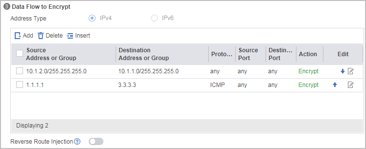
- Choose , click Add.
- Set an IP address for each interface and assign the interfaces to security zones.
- Configure FW_A (Headquarters).
- Set an IP address for each interface and assign the interfaces to security zones.
- Choose .
Click
of GE0/0/1 and set the following parameters:Zone
untrust
IPv4
IP Address
3.3.3.3/24
Management Access
Ping
In this example, FW_B pings the IP address of the public interface GE0/0/1 on FW_A to check the tunnel quality. Therefore, Management Access must be set to Ping for GE0/0/1. Otherwise, FW_A cannot respond to the ping request from FW_B.
- Click OK.
Click
of GE0/0/3 and set the following parameters:Zone
trust
IPv4
IP Address
10.1.1.1/24
- Click OK.
- Configure security policies to allow specific subnets to communicate.
Click Add and set the parameters of the security policy for the Trust->Untrust interzone as follows:
Name
policy_ipsec_1
Source Zone
trust
Destination Zone
untrust
Source Address/Region
10.1.1.0/24
Destination Address/Region
10.1.2.0/24
Action
Permit
- Click OK.
Repeat preceding steps to configure security policies for the Untrust -> Trust, Untrust -> Local, and Local -> Untrust interzones.
The parameters of the security policy for the Untrust -> Trust interzone are as follows:
Name
policy_ipsec_2
Source Zone
untrust
Destination Zone
trust
Source Address/Region
10.1.2.0/24
Destination Address/Region
10.1.1.0/24
Action
Permit
The parameters of the security policy for the Untrust -> Local interzone are as follows:
Name
policy_ipsec_3
Source Zone
untrust
Destination Zone
local
Source Address/Region
1.1.1.1/32
2.2.2.2/32
Destination Address/Region
3.3.3.3/32
Action
Permit
The parameters of the security policy for the Local -> Untrust interzone are as follows:
Name
policy_ipsec_4
Source Zone
local
Destination Zone
untrust
Source Address/Region
3.3.3.3/32
Destination Address/Region
1.1.1.1/32
2.2.2.2/32
Action
Permit
The local-untrust interzone policy controls whether IKE negotiation packets can pass through the FW. This policy can use the source and destination addresses, protocol, or port as the matching condition. In this example, the source and destination addresses are used as the matching condition. To use the protocol or port as the matching condition, you need to enable ESP and port 500 for UDP (port 4500 also in NAT traversal scenarios).
- Configure the IPSec tunnel on FW_A.
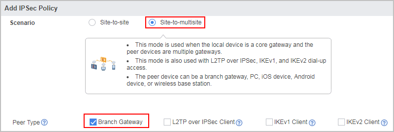
Select Site-to-multisite as Scenario and Branch gateway as Peer Type.
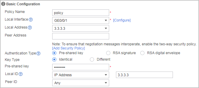
Configure Basic Configuration as follows. The headquarters needs to be accessed by multiple branches. Therefore, do not specify the remote gateway addresses. The pre-shared key is Admin@123.
Under Data Flow to Encrypt, click Add to add a data flow as follows.
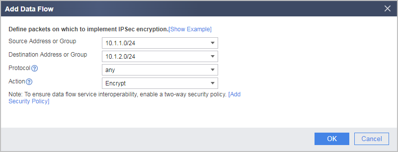
Under Data Flow to Encrypt, click Add to add a data flow as follows.
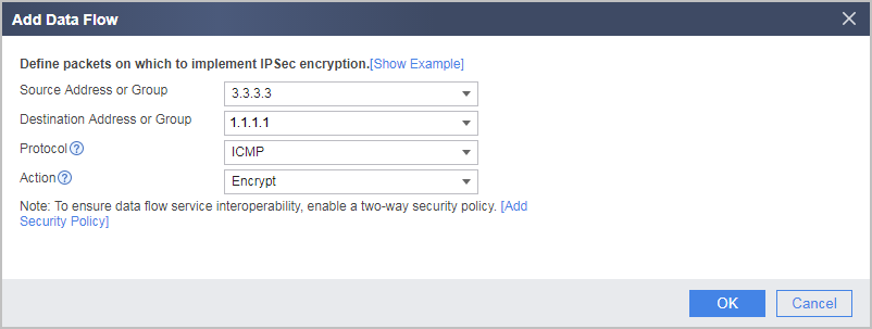
This data flow rule guides tunnel detection packets to a specific IPSec tunnel.
Under Data Flow to Encrypt, click Add to add a data flow as follows.
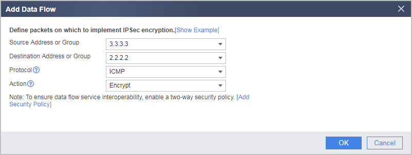
This data flow rule guides tunnel detection packets to a specific IPSec tunnel.
Under Data Flow to Encrypt, select Reverse Route Injection so that the headquarters can automatically generate a route to branches.
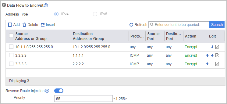
When FW_B uses the local and peer IPSec tunnel interface IP addresses as the source and destination IP addresses of detection packets respectively. If reverse route injection is enabled, you need add the specific route to the interface connecting the gateway in each branch office to the Internet on the gateway in the headquarters. The destination IP address of the route is the IP address (32-bit mask) of the peer IPSec tunnel interface. The route has a higher priority than the UNR route automatically generated during reverse route injection (the value of priority is lower than 65 in this example).
- Set an IP address for each interface and assign the interfaces to security zones.
Configuration Verification
After the configuration is complete, the branch first uses Link 1 (1.1.1.1 -> 3.3.3.3) to establish an IPSec tunnel. The IPSec Negotiation Status value is Succeeded, and the branch can access the headquarters.

Shut down GE0/0/1 on FW_B at the branch, FW_B automatically uses Link 2 (2.2.2.2 -> 3.3.3.3) to establish an IPSec tunnel.

In V600R007C20SPC500 and later versions, Policy Type can be displayed in the IPSec Policy List.
Configuration Scripts
Configuration script on FW_A (Headquarters):
#
acl number 3000
 rule 5 permit ip source 10.1.1.0 0.0.0.255 destination 10.1.2.0 0.0.0.255
 rule 10 permit icmp source 3.3.3.3 0 destination 1.1.1.1 0
 rule 15 permit icmp source 3.3.3.3 0 destination 2.2.2.2 0
#
ike proposal 1
 authentication-algorithm sha2-256
 integrity-algorithm aes-xcbc-96 hmac-sha2-256
#
ike peer ike183144438250
 exchange-mode auto
 pre-shared-key %$%$921NG0I(@0aT8y@GhOS97G>5%$%$
 ike negotiate compatible
 ike-proposal 1
 remote-id-type none
#
ipsec proposal prop18314443825
 encapsulation-mode auto
 esp authentication-algorithm sha2-256
#
ipsec policy-template tpl183144438250 1
 security acl 3000
 ike-peer ike183144438250
 alias policy
 proposal prop18314443825
 route inject dynamic preference 65
 sa duration traffic-based 200000000
 sa duration time-based 3600
#
ipsec policy ipsec1831444383 10000 isakmp template tpl183144438250
#
interface GigabitEthernet0/0/3
 ip address 10.1.1.1 255.255.255.0
#
interface GigabitEthernet0/0/1
 ip address 3.3.3.3 255.255.255.0
 ipsec policy ipsec1831444383
 service-manage ping permit
#
firewall zone trust
 set priority 85
 add interface GigabitEthernet0/0/3
#
firewall zone untrust
 set priority 5
 add interface GigabitEthernet0/0/1
#
security-policy
  rule name policy_ipsec_1
    source-zone trust
    destination-zone untrust
    source-address 10.1.1.0 24
    destination-address 10.1.2.0 24
    action permit
  rule name policy_ipsec_2
    source-zone untrust
    destination-zone trust
    source-address 10.1.2.0 24
    destination-address 10.1.1.0 24
    action permit
  rule name policy_ipsec_3
    source-zone untrust
    destination-zone local
    source-address 1.1.1.1 32
    source-address 2.2.2.2 32
    destination-address 3.3.3.3 32
    action permit
  rule name policy_ipsec_4
    source-zone local
    destination-zone untrust
    source-address 3.3.3.3 32
    destination-address 1.1.1.1 32
    destination-address 2.2.2.2 32
    action permit
Configuration script on FW_B (Branch):
#
acl number 3000
 rule 5 permit ip source 10.1.2.0 0.0.0.255 destination 10.1.1.0 0.0.0.255
#
ike proposal 1
 authentication-algorithm sha2-256
 integrity-algorithm aes-xcbc-96 hmac-sha2-256
#
ike peer ike183104627184
 exchange-mode auto
 pre-shared-key %$%$QoAR'zsMp!&5y%7qm\)XOZQH%$%$
 ike-proposal 1
 remote-id-type none
 remote-address 3.3.3.3
#
ipsec proposal prop18310462718
 encapsulation-mode auto
 esp authentication-algorithm sha2-256
#
ipsec smart-link profile prop18310462718
 link-quality-detection interval 1 number 10
 auto-switch cycles 3
 link-quality-threshold loss 30
 link-quality-threshold delay 500
 smart-link enable
 link 1 interface GigabitEthernet0/0/0 local 1.1.1.1 nexthop 1.1.1.254 remote 3.3.3.3
 link 2 interface GigabitEthernet0/0/3 local 2.2.2.2 nexthop 2.2.2.254 remote 3.3.3.3
#
ipsec policy ipsec1831046272 10000 isakmp
 security acl 3000
 ike-peer ike183104627184
 alias policy
 proposal prop18310462718
 sa duration traffic-based 200000000
 sa duration time-based 3600
 smart-link profile prop18310462718
#
interface GigabitEthernet0/0/3
 ip address 10.1.2.1 255.255.255.0
#
interface GigabitEthernet0/0/2
 ip address 2.2.2.2 255.255.255.0
 gateway 2.2.2.254
#
interface GigabitEthernet0/0/1
 ip address 1.1.1.1 255.255.255.0
 gateway 1.1.1.254
#
firewall zone trust
 set priority 85
 add interface GigabitEthernet0/0/3
#
firewall zone untrust
 set priority 5
 add interface GigabitEthernet0/0/1
 add interface GigabitEthernet0/0/2
#
security-policy
  rule name policy_ipsec_1
    source-zone trust
    destination-zone untrust
    source-address 10.1.2.0 24
    destination-address 10.1.1.0 24
    action permit
  rule name policy_ipsec_2
    source-zone untrust
    destination-zone trust
    source-address 10.1.1.0 24
    destination-address 10.1.2.0 24
    action permit
  rule name policy_ipsec_3
    source-zone untrust
    destination-zone local
    source-address 3.3.3.3 32
    destination-address 1.1.1.1 32
    destination-address 2.2.2.2 32
    action permit
  rule name policy_ipsec_4
    source-zone local
    destination-zone untrust
    source-address 1.1.1.1 32
    source-address 2.2.2.2 32
    destination-address 3.3.3.3 32
    action permit