Web: Example for Configuring an IPSec VPN Tunnel Through IKE Negotiation When a NAT Device Is Deployed Between Two Gateways (the Headquarters Authenticates Branches by Name)
Networking Requirement
The network environment of Figure 1 is as follows:
The headquarters network (10.1.1.0/24) is connected to FW_A through interface GigabitEthernet 0/0/1.
The branch network (10.1.2.0/24) is connected to FW_C through interface GigabitEthernet 0/0/1.
- FW_B serves as a NAT gateway. Branch users must pass through FW_B to access the headquarters network.
Data on the headquarters server is confidential and therefore cannot be transmitted on the Internet without protection. To ensure data security, an IPSec tunnel needs to be established between the headquarters and branch to encrypt the data when the branch employees access the headquarters server.
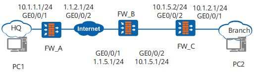
Data Plan
Item |
Data |
|---|---|
FW_A |
Interface number: GigabitEthernet 0/0/1 IP address: 10.1.1.1/24 Security zone: Trust |
FW_A |
Interface number: GigabitEthernet 0/0/2 IP address: 1.1.2.1/24 Security zone: Untrust |
FW_A |
IPSec configuration Peer IP address: 1.1.5.1 Authentication type: pre-shared key Pre-shared key: Test!1234 Local ID type: IP Peer ID type: FQDN Peer ID: branch |
FW_B |
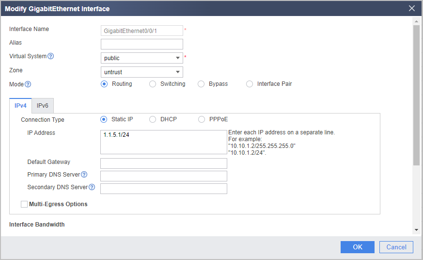
Interface number: GigabitEthernet 0/0/1 IP address: 1.1.5.1/24 Security zone: Untrust |
FW_B |
Interface number: GigabitEthernet 0/0/2 IP address: 10.1.5.1/24 Security zone: Trust |
FW_B |
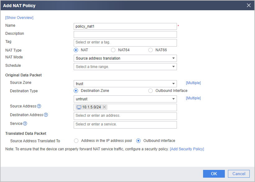
NAT configuration NAT Mode: Source address translation Source Address Translated To: Outbound interface |
FW_C |
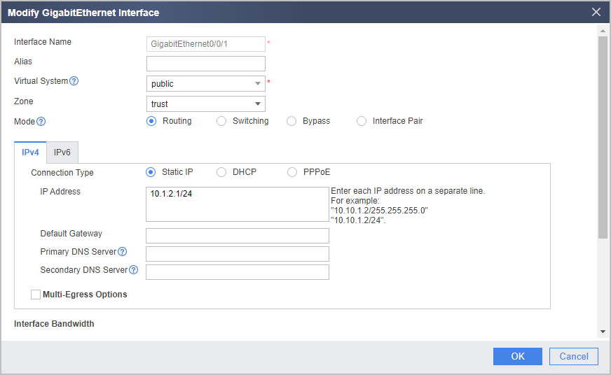
Interface number: GigabitEthernet 0/0/1 IP address: 10.1.2.1/24 Security zone: Trust |
FW_C |
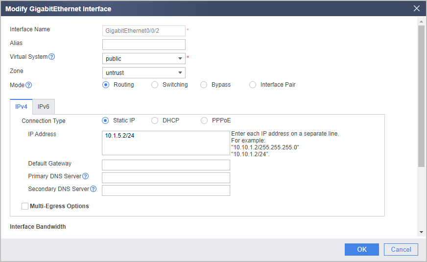
Interface number: GigabitEthernet 0/0/2 IP address: 10.1.5.2/24 Security zone: Untrust |
FW_C |
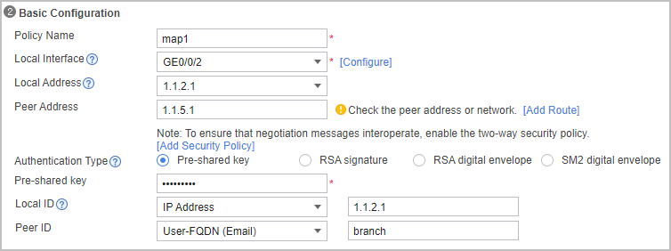
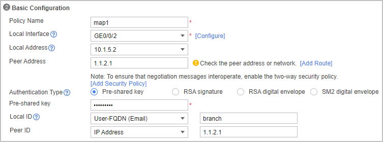
IPSec configuration Peer IP address: 1.1.2.1 Authentication type: pre-shared key Pre-shared key: Test!1234 Local ID type: FQDN Peer ID type: IP Local ID: branch |
Procedure
- Set parameters on FW_A.
- Set an IP address for each interface, assign interfaces to security zones, and complete basic parameter settings.
- Choose .
- Click
 next to GE0/0/1 and configure parameters as follows.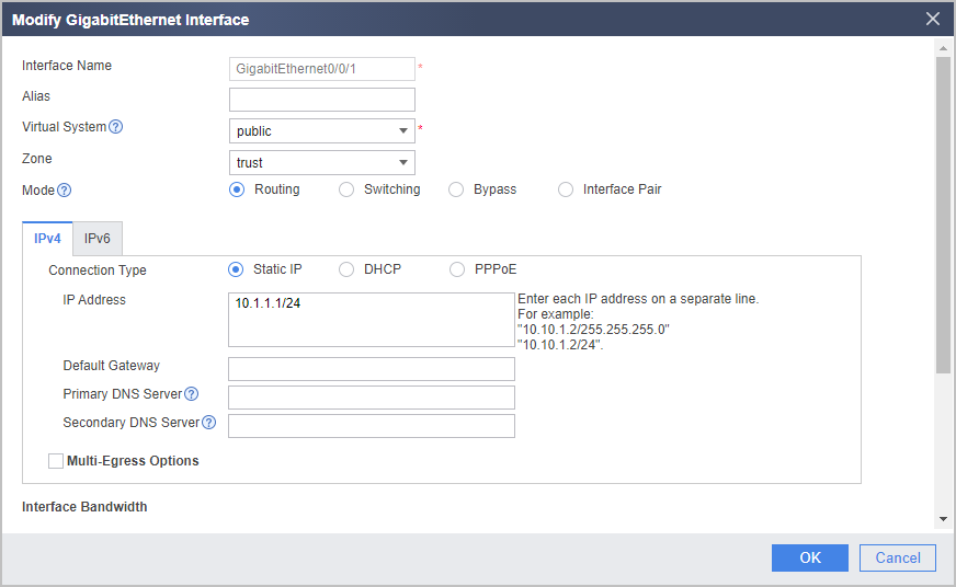
- Click OK.
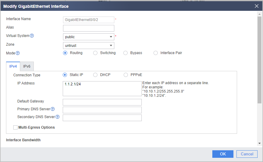
- Repeat the preceding steps to configure the parameters for GE0/0/2.
- Configure security policies to permit IPSec negotiation packets and service packets.
- Choose .
- Choose Add Security Policy and set the following parameters for the Trust-to-Untrust interzone policy.
Name
policy1
Source Zone
trust
Destination Zone
untrust
Source Address/Region
10.1.1.0/24
Destination Address/Region
10.1.2.0/24
Action
Permit
- Click OK.
- Repeat the preceding steps to configure the Untrust-to-Trust, Local-to-Untrust, and Untrust-to-Local interzone policies.The parameters of the Untrust-to-Trust interzone policy are as follows.
Name
policy2
Source Zone
untrust
Destination Zone
trust
Source Address/Region
10.1.2.0/24
Destination Address/Region
10.1.1.0/24
Action
Permit

The Local-Untrust interzone policy controls whether IKE negotiation packets can pass through the FW. This policy can use the source and destination addresses, protocol, or port as the matching condition. In this example, the source and destination addresses are used as the matching condition. To use the protocol or port as the matching condition, you need to enable ESP and port 500 for UDP (port 4500 also in NAT traversal scenarios).
The parameters of the Local-to-Untrust interzone policy are as follows.
Name
policy3
Source Zone
local
Destination Zone
untrust
Source Address/Region
1.1.2.1/32
Destination Address/Region
1.1.5.1/32
Action
Permit
The parameters of the Untrust-to-Local interzone policy are as follows.
Name
policy4
Source Zone
untrust
Destination Zone
local
Source Address/Region
1.1.5.1/32
Destination Address/Region
1.1.2.1/32
Action
Permit
Configure security policies between the Local and Untrust zones to allow devices on both ends of an IPSec tunnel to communicate with each other.
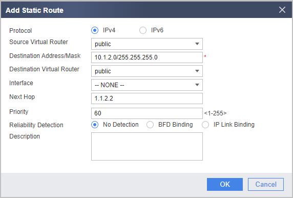
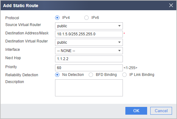
- Configure static routes to the branches. Assume that the next hop of the static routes is 1.1.2.2.
- Choose .
- Click Add and configure the parameters as follows.
- Configure an IPSec tunnel for FW_A.
- Configure basic information of an IPSec policy, specify the peer gateway, and set the pre-shared key to Test!1234.
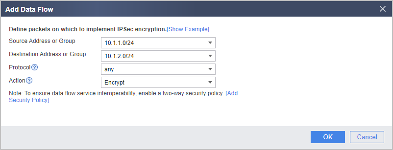
- In Data Flow to Encrypt, click Add, and add a data flow as follows.
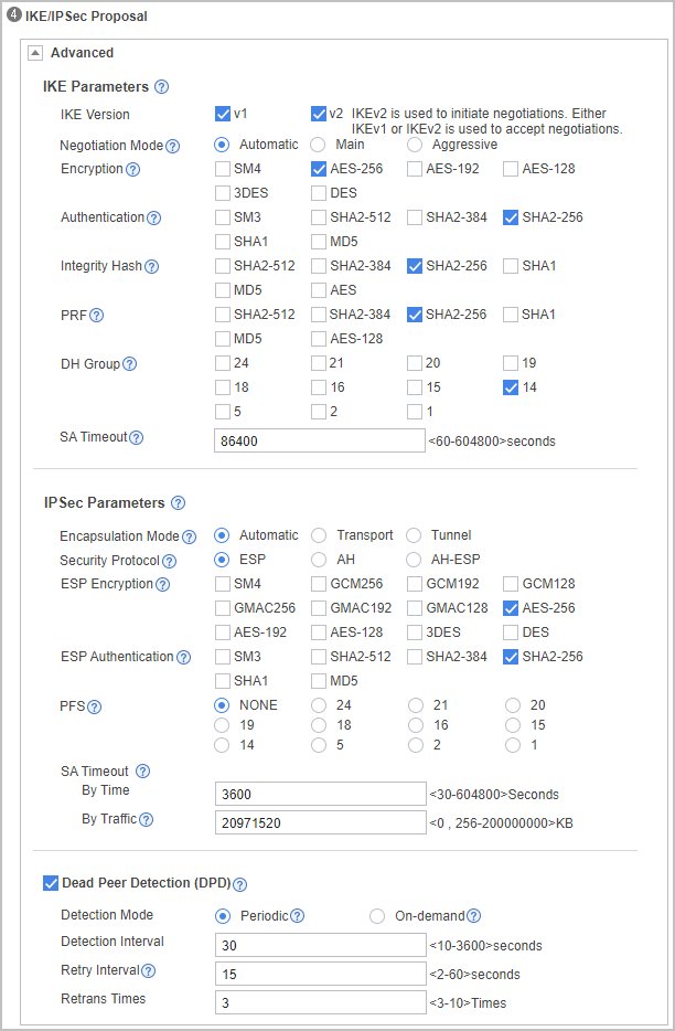
- Expand the Advanced area in IKE/IPSec Proposal, and configure IKE and IPSec parameters. Note that security proposals on the two ends of a tunnel must be the same.
- Click Apply. The IPSec configuration for FW_A is completed.
- Set an IP address for each interface, assign interfaces to security zones, and complete basic parameter settings.
- Configure FW_C.
- Set an IP address for each interface, assign interfaces to security zones, and complete basic parameter settings.
- Configure security policies to permit IPSec negotiation packets and service packets.
- Choose .
- Click Add Security Policy and set the following parameters for the Trust-to-Untrust interzone policy.
Name
policy1
Source Zone
trust
Destination Zone
untrust
Source Address/Region
10.1.2.0/24
Destination Address/Region
10.1.1.0/24
Action
Permit
- Click OK.
- Repeat the preceding steps to configure the Untrust-to-Trust, Local-to-Untrust, and Untrust-to-Local interzone policies.The parameters of the Untrust-to-Trust interzone policy are as follows.
Name
policy2
Source Zone
untrust
Destination Zone
trust
Source Address/Region
10.1.1.0/24
Destination Address/Region
10.1.2.0/24
Action
Permit
The Local-Untrust interzone policy controls whether IKE negotiation packets can pass through the FW. This policy can use the source and destination addresses, protocol, or port as the matching condition. In this example, the source and destination addresses are used as the matching condition. To use the protocol or port as the matching condition, you need to enable ESP and port 500 for UDP (port 4500 also in NAT traversal scenarios).
The parameters of the Local-to-Untrust interzone policy are as follows.
Name
policy3
Source Zone
local
Destination Zone
untrust
Source Address/Region
10.1.5.2/32
Destination Address/Region
1.1.2.1/32
Action
Permit
The parameters of the Untrust-to-Local interzone policy are as follows.
Name
policy4
Source Zone
untrust
Destination Zone
local
Source Address/Region
1.1.2.1/32
Destination Address/Region
10.1.5.2/32
Action
Permit
Configure security policies between the Local and Untrust zones to allow devices on both ends of an IPSec tunnel to communicate with each other.
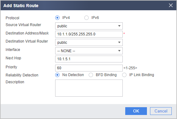
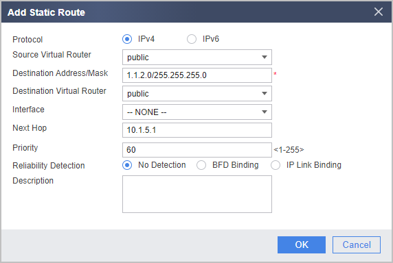
- Configure static routes to the headquarters. Assume that the next hop of the static routes is 10.1.5.1.
- Choose .
- Click Add and configure the parameters as follows.
- Configure an IPSec tunnel for FW_C.
- Configure basic information of an IPSec policy, specify the peer gateway, and set the pre-shared key to Test!1234.
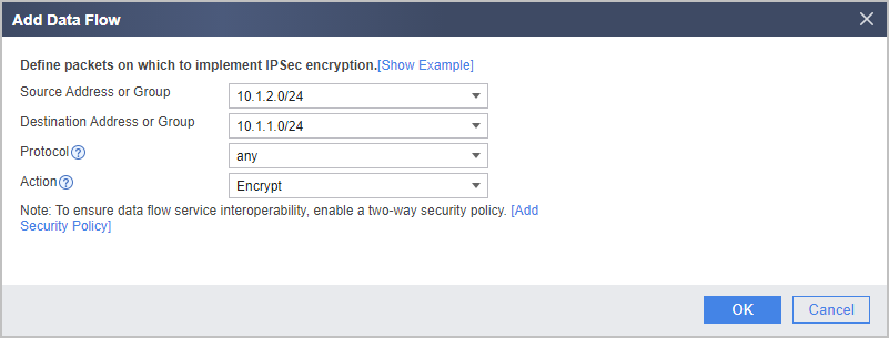
- In Data Flow to Encrypt, click Add and add a data flow as follows.
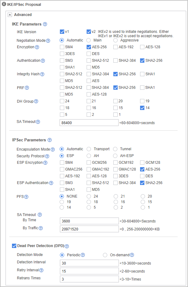
- Expand the Advanced area in IKE/IPSec Proposal, and configure IKE and IPSec parameters. Note that security proposals on the two ends of a tunnel must be the same.
- Click Apply. The IPSec configuration for FW is completed.
- Configure FW_B (the NAT gateway).
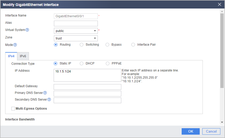
- Set an IP address for each interface, assign interfaces to security zones, and complete basic parameter settings.
- Configure an NAT policy for FW_B.


Verification
After the configuration is complete, PC2 can communicate with PC1 and access the public network.
PC2 can ping the interface IP address 1.1.2.1 of FW_A. Meanwhile, you can view NAT session entries on FW_B.
<FW_B> display firewall session table
  Current Total Sessions : 2
  udp  VPN:public --> public 10.1.5.2:500[1.1.5.1:2048]-->1.1.2.1:500
  udp  VPN:public --> public 10.1.5.2:4500[1.1.5.1:2048]-->1.1.2.1:4500
On FW_A, you can view IKE SA information.
<FW_A> display ike sa
IKE SA information :
    Conn-ID     Peer            VPN   Flag(s)  Phase  RemoteType  RemoteID
  -----------------------------------------------------------------------------
    83887864    1.1.5.1:500           RD|A     v2:2   FQDN        branch
    83887652    1.1.5.1:500           RD|A     v2:1   FQDN        branch

  Number of IKE SA : 2
  -------------------------------------------------------------------------------

  Flag Description:
  RD--READY   ST--STAYALIVE   RL--REPLACED   FD--FADING   TO--TIMEOUT
  HRT--HEARTBEAT   LKG--LAST KNOWN GOOD SEQ NO.   BCK--BACKED UP
  M--ACTIVE   S--STANDBY   A--ALONE  NEG--NEGOTIATING
On FW_C, you can view the IKE SA whose peer end is the headquarters. FW_C is the initiator and the flag bit is ST.
<FW_C> display ike sa IKE SA information : Conn-ID Peer VPN Flag(s) Phase RemoteType RemoteID ----------------------------------------------------------------------------- 62887864 1.1.2.1:500 RD|ST|A v2:2 IP 1.1.2.1 62887652 1.1.2.1:500 RD|ST|A v2:1 IP 1.1.2.1 Number of IKE SA : 2 ------------------------------------------------------------------------------- Flag Description: RD--READY ST--STAYALIVE RL--REPLACED FD--FADING TO--TIMEOUT HRT--HEARTBEAT LKG--LAST KNOWN GOOD SEQ NO. BCK--BACKED UP M--ACTIVE S--STANDBY A--ALONE NEG--NEGOTIATING- On FW_A, you can view a pair of IPSec SAs corresponding to FW_C.
<FW_A> display ipsec sa brief Current ipsec sa num:2 Spu board slot 1, cpu 1 ipsec sa information: Number of SAs:2 Src address Dst address SPI VPN Protocol Algorithm ------------------------------------------------------------------------------- 1.1.2.1 1.1.5.1 3923280450 ESP E:AES-256 A:SHA2_256_128 1.1.5.1 1.1.2.1 2676437093 ESP E:AES-256 A:SHA2_256_128 - On FW_C, you can view a pair of IPSec SAs.
<FW_C> display ipsec sa brief
Current ipsec sa num:2

Spu board slot 1, cpu 1 ipsec sa information:
Number of SAs:2
    Src address   Dst address      SPI         VPN  Protocol     Algorithm
-------------------------------------------------------------------------------
    10.1.5.2         1.1.2.1       2179965693       ESP     E:AES-256 A:SHA2_256_128
    1.1.2.1         10.1.5.2       3813759530       ESP     E:AES-256 A:SHA2_256_128
Follow-up Procedure
Configuration Files
-
#
 sysname FW_A
#
acl number 3000
 rule 5 permit ip source 10.1.1.0 0.0.0.255 destination 10.1.2.0 0.0.0.255
#
ike proposal 10
 encryption-algorithm aes-256
 dh group14
 authentication-algorithm sha2-256
 authentication-method pre-share
 integrity-algorithm hmac-sha2-256
 prf hmac-sha2-256
#
ike peer c
 pre-shared-key %^%#2|{=/i>8VTWdH7EO&kuCEYtG%^%#
 ike-proposal 10
 local-id-type ip
 remote-id-type fqdn
 remote-id branch
 remote-address 1.1.5.1
#
ipsec proposal tran1
 esp authentication-algorithm sha2-256
 esp encryption-algorithm aes-256
#
ipsec policy map1 10 isakmp
 security acl 3000
 ike-peer c
 proposal tran1
#
interface GigabitEthernet0/0/1
 undo shutdown
 ip address 10.1.1.1 255.255.255.0
#
interface GigabitEthernet0/0/2
 undo shutdown
 ip address 1.1.2.1 255.255.255.0
 ipsec policy map1
#
firewall zone trust
 set priority 85
 add interface GigabitEthernet0/0/1
#
firewall zone untrust
 set priority 5
 add interface GigabitEthernet0/0/2
#
ip route-static 10.1.2.0 255.255.255.0 1.1.2.2
ip route-static 10.1.5.0 255.255.255.0 1.1.2.2
#
security-policy
  rule name policy1
    source-zone trust
    destination-zone untrust
    source-address 10.1.1.0 24
    destination-address 10.1.2.0 24
    action permit
  rule name policy2
    source-zone untrust
    destination-zone trust
    source-address 10.1.2.0 24
    destination-address 10.1.1.0 24
    action permit
  rule name policy3
    source-zone local
    destination-zone untrust
    source-address 1.1.2.1 32
    destination-address 1.1.5.1 32
    action permit
  rule name policy4
    source-zone untrust
    destination-zone local
    source-address 1.1.5.1 32
    destination-address 1.1.2.1 32
    action permit
#
return
-
#
 sysname FW_C
#
acl number 3000
 rule 5 permit ip source 10.1.2.0 0.0.0.255 destination 10.1.1.0 0.0.0.255
#
ike proposal 10
  encryption-algorithm aes-256
  dh group14
  authentication-algorithm sha2-256
  authentication-method pre-share
  integrity-algorithm hmac-sha2-256
  prf hmac-sha2-256
#
ike peer a
 pre-shared-key %^%#nAyDSdHR4J#AK|PYA,D"/FZ|%^%#
 ike-proposal 10
 local-id-type fqdn
 remote-id-type ip
 local-id branch
 remote-address 1.1.2.1
#
ipsec proposal tran1
 esp authentication-algorithm sha2-256
 esp encryption-algorithm aes-256
#
ipsec policy map1 10 isakmp
 security acl 3000
 ike-peer a
 proposal tran1
#
interface GigabitEthernet0/0/1
 undo shutdown
 ip address 10.1.2.1 255.255.255.0
#
interface GigabitEthernet0/0/2
 undo shutdown
 ip address 10.1.5.2 255.255.255.0
 ipsec policy map1
#
firewall zone trust
 set priority 85
 add interface GigabitEthernet0/0/1
#
firewall zone untrust
 set priority 5
 add interface GigabitEthernet0/0/2
#
ip route-static 1.1.2.0 255.255.255.0 10.1.5.1
ip route-static 10.1.1.0 255.255.255.0 10.1.5.1
#
security-policy
  rule name policy1
    source-zone trust
    destination-zone untrust
    source-address 10.1.2.0 24
    destination-address 10.1.1.0 24
    action permit
  rule name policy2
    source-zone untrust
    destination-zone trust
    source-address 10.1.1.0 24
    destination-address 10.1.2.0 24
    action permit
  rule name policy3
    source-zone local
    destination-zone untrust
    source-address 10.1.5.2 32
    destination-address 1.1.2.1 32
    action permit
  rule name policy4
    source-zone untrust
    destination-zone local
    source-address 1.1.2.1 32
    destination-address 10.1.5.2 32
    action permit
#
return
-
#
 sysname FW_B
#
interface GigabitEthernet0/0/1
 undo shutdown
 ip address 1.1.5.1 255.255.255.0
#
interface GigabitEthernet0/0/2
 undo shutdown
 ip address 10.1.5.1 255.255.255.0
#
firewall zone trust
 set priority 85
 add interface GigabitEthernet0/0/2
#
firewall zone untrust
 set priority 5
 add interface GigabitEthernet0/0/1
#
security-policy
  rule name policy1
    source-zone trust
    destination-zone untrust
    source-address 10.1.5.2 32
    destination-address 1.1.2.1 32
    action permit
  rule name policy2
    source-zone untrust
    destination-zone trust
    source-address 1.1.2.1 32
    destination-address 10.1.5.2 32
    action permit
#
nat-policy
  rule name policy_nat1
    source-zone trust
    destination-zone untrust
    source-address 10.1.5.0 24
    action source-nat easy-ip
#
return
-