Web: Example for Applying IPSec Services in Load Balancing Scenarios
This section provides an example for configuring IPSec services in load balancing scenarios.
Networking Requirements
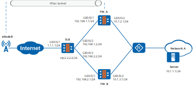
As shown in Figure 1, the service load balancer (SLB) at the network egress distributes traffic from the eNodeB to network A. FW_A and FW_B are IPSec gateways, forming a cluster server. For the security of access from the eNodeB to network A, you must establish an IPSec tunnel between the eNodeB and FW (FW_A and FW_B) and configure the SLB to evenly distribute IPSec traffic from the eNodeB to the FW. That is, traffic can be evenly distributed to FW_A and FW_B.
Configuration Roadmap
- Configure the SLB.

In this example, the FW serves as the SLB.
-
The configuration of FW_B is similar to that of FW_A, and will not be described in detail.
- Configure the SLB.
- Set the IP addresses of the interfaces and add the interfaces to corresponding security zones.
Choose . Locate the desired interface and click Edit of the interface to set interface parameters as listed in the following table.
Interface
GigabitEthernet 0/0/1
GigabitEthernet 0/0/2
GigabitEthernet 0/0/3
Zone
untrust
dmz
dmz
IPv4
IP Address
1.1.1.1/24
192.168.1.2/24
192.168.2.2/24
- Configure interzone security policies.
# Configure security policies between users and servers. Choose , choose , and set the parameters.
Name
untrust_dmz_inbound
Source Zone
Untrust
Destination Zone
DMZ
Source Address/Region
Any
Destination Address/Region
192.168.1.0/24
192.168.2.0/24
Action
Permit
- Configure server load balancing.
- Choose , click Add, and set the parameters.
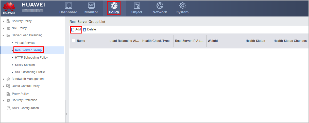
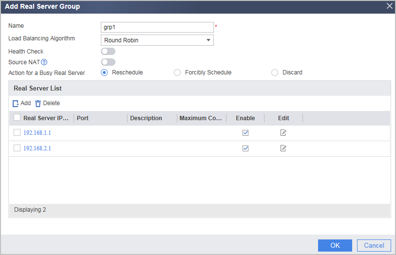
- Click OK.
- Choose , click Add, and set the parameters.
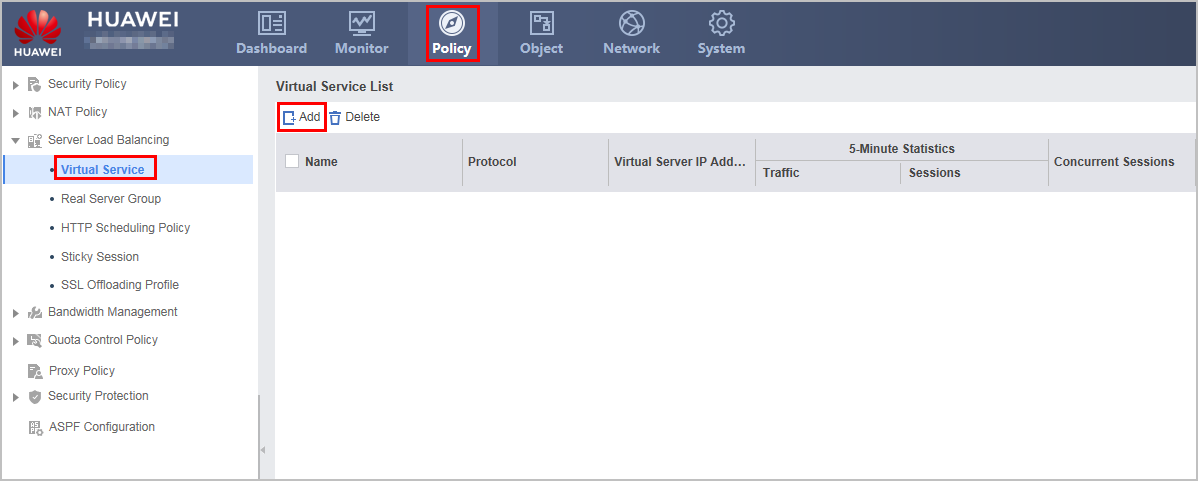
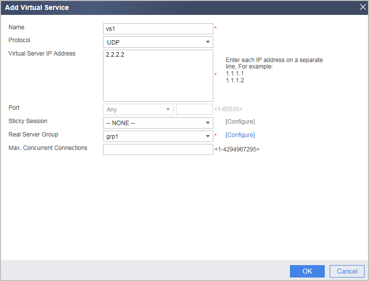
- Click OK.
- Choose , click Add, and set the parameters.
- Set the IP addresses of the interfaces and add the interfaces to corresponding security zones.
- Configure FW_A.
- Set interface IP addresses and assign the interfaces to security zones.
- Configure security policies to allow specific subnets to communicate.
Click Add and set the following parameters.
Name
ipsec_tu
Source Zone
Trust
Destination Zone
Untrust
Source Address/Region
10.1.1.0/24
Action
Permit
- Click OK.
Repeat the preceding steps to configure Untrust -> Trust, Untrust -> Local, and Local -> Untrust interzone policies.
The parameters of the security policy for the Untrust -> Trust interzone are as follows:
Name
ipsec_ut
Source Zone
untrust
Destination Zone
trust
Destination Address/Region
10.1.1.0/24
Action
Permit
The parameters of the Untrust -> Local interzone policy are as follows.
Name
ipsec_ul
Source Zone
untrust
Destination Zone
local
Destination Address/Region
192.168.1.1/32
Action
Permit
The parameters of the Local -> Untrust interzone policy are as follows.
Name
ipsec_lu
Source Zone
local
Destination Zone
untrust
Source Address/Region
192.168.1.1/32
Action
Permit
The local-untrust interzone policy controls whether IKE negotiation packets can pass through the FW. This policy can use the source and destination addresses, protocol, or port as the matching condition. In this example, the source and destination addresses are used as the matching condition. To use the protocol or port as the matching condition, you need to enable ESP and port 500 for UDP (port 4500 also in NAT traversal scenarios).
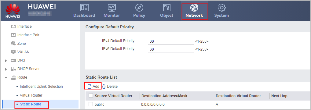
- Configure a route from the FW_A to the eNodeB and a route from FW_A to server.
In this example, the next hop from FW_A to the eNodeB is 192.168.1.2, and the next hop of the route to the server is 10.1.2.2.
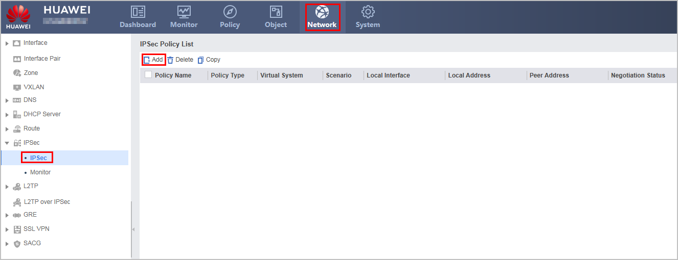
- Configure an IPSec tunnel.
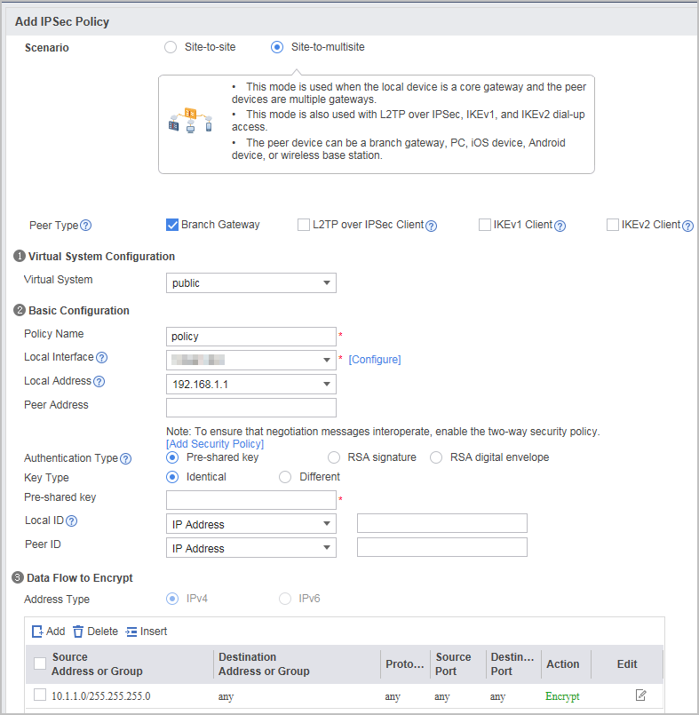
Choose , click Add, and set the parameters.
In this example, the pre-shared key is Admin@123, and the default proposal parameter values are used. To change the value of a specific parameter, unfold in IKE/IPSec Proposal. Proposal configurations on the two ends of the tunnel must be the same.
If link health check is enabled on the SLB, you must configure a rule to block traffic from 192.168.1.2. Otherwise, the link health check function is invalid.
- Click Apply. The configuration of FW_A is complete.
- Configure FW_B.
The configuration of FW_B is similar to that of FW_A. You can configure FW_B by referring to the configuration of FW_A.

Verification
- Check static server map entries on the SLB. If corresponding server map entries exist, the server load balancing is successfully configured.
[SLB] display firewall server-map static
 Current Total Server-map : 2
 Type: SLB,  ANY -> 2.2.2.2[grp1/0],  Zone:---,  protocol:udp
 Vpn: public -> public
- View the session table on the SLB. If a session exists and the destination IP address of the request packet is changed from the virtual server IP address to the IP address of a real server, the server load balancing is successfully configured.
[SLB] display firewall session table verbose
Current Total Sessions : 2
 udp  VPN: public --> public  ID: c487fb5ba7d8458875c5758ad84
 Zone: trust --> trust  TTL: 00:02:00  Left: 00:02:00
 Recv Interface: GigabitEthernet0/0/0
 Interface: GigabitEthernet0/0/1  NextHop: 3.3.3.1  MAC: 5254-0012-3513
 <--packets: 58851 bytes: 5,094,045 --> packets: 58851 bytes: 5,094,029
 1.1.1.2:4500[1.1.1.1:2049] --> 2.2.2.2:4500[192.168.1.1:4500] PolicyName: ---

udp  VPN: public --> public  ID: c487fb5ba7d8300f6b45758ad81
 Zone: trust --> trust  TTL: 00:02:00  Left: 00:01:58
 Recv Interface: GigabitEthernet0/0/0
 Interface: GigabitEthernet0/0/1  NextHop: 3.3.3.1  MAC: 5254-0012-3513
 <--packets: 58858 bytes: 5,094,842 --> packets: 58857 bytes: 5,095,021
 1.1.1.3:4500[1.1.1.1:2048] --> 2.2.2.2:4500[192.168.2.1:4500] PolicyName: ---
- After a while, view the running status of the virtual server on the SLB. The ratio of total sessions on the two real servers is 1:1.
[SLB] display slb vserver verbose vs1 Virtual Server Information(Total 1) -------------------------------------------------------------------------------- ------------- Virtual Server Name : vsr1 Virtual Server ID : 0 Virtual Server IP : 2.2.2.2 Protocol : udp Virtual Server Port : any Http X-forward Enable : Disable Virtual Server Max-conn : -- Persistence Name/ID : a/0 Persistence Type : source-ip Group Name : grp1 Group ID : 0 Current Connection : 2 RserverID IP Address Weight Status Ratio TotalSession CurSession 0 192.168.1.1 1 Admin-Active 50.55% 10 2 0 192.168.2.1 1 Admin-Active 49.45% 11 2 -------------------------------------------------------------------------------- - Run the display ipsec sa on FW_A. You can see that the IPSec tunnel has been established.
[FW] display ipsec sa
2016-06-13 05:49:46.570

ipsec sa information:

===============================
Interface: GigabitEthernet0/0/1
===============================

  -----------------------------
  IPSec policy name: "map1"
  Sequence number  : 1
  Acl group        : 3000
  Acl rule         : 5
  Mode             : Template
  -----------------------------
    Connection ID     : 339
    Encapsulation mode: Tunnel
    Tunnel local      : 192.168.1.2
    Tunnel remote     : 192.168.1.2
    Flow source       : 10.1.1.0/255.255.255.0 0/0
    Flow destination  : 10.1.4.0/255.255.255.255 0/0

    [Outbound ESP SAs]
      SPI: 1534118999 (0x5b70cc57)
      Proposal: ESP-ENCRYPT-AES-256 ESP-AUTH-SHA2-256-128
      SA remaining key duration (kilobytes/sec): 10485760/3490
      Max sent sequence-number: 1
      UDP encapsulation used for NAT traversal: Y
      SA encrypted packets (number/bytes): 0/0

    [Inbound ESP SAs]
      SPI: 1743339630 (0x67e9406e)
      Proposal: ESP-ENCRYPT-AES-256 ESP-AUTH-SHA2-256-128
      SA remaining key duration (kilobytes/sec): 10485760/3490
      Max received sequence-number: 1
      UDP encapsulation used for NAT traversal: Y
      SA decrypted packets (number/bytes): 0/0
      Anti-replay : Enable
      Anti-replay window size: 1024
Configuration Scripts
Configuration script of the SLB:
#
 sysname SLB
#
 slb enable
#
interface GigabitEthernet0/0/1
 ip address 1.1.1.1 255.255.255.0
#
interface GigabitEthernet0/0/2
 ip address 192.168.1.2 255.255.255.0
#
interface GigabitEthernet0/0/3
 ip address 192.168.2.2 255.255.255.0
#
firewall zone untrust
 set priority 5
 add interface GigabitEthernet0/0/1
#
firewall zone dmz
 set priority 50
 add interface GigabitEthernet0/0/2
 add interface GigabitEthernet0/0/3
#
 slb
  group 1 grp1
   metric roundrobin
   rserver 1 rip 192.168.1.1 weight 1
   rserver 2 rip 192.168.2.1 weight 1
  vserver 1 vs1
   vip 1 2.2.2.2
   protocol udp
   vport any
   group grp1
#
security-policy
 rule name untrust_dmz_inbound
  source-zone untrust
  destination-zone dmz
  destination-address 192.168.1.0 24
  destination-address 192.168.2.0 24
  action permit
#
return
Configuration script of FW_A:
#
acl 3000
 rule 5 permit ip source 10.1.1.0 0.0.0.255
#
ipsec proposal tran1
  esp authentication-algorithm sha2-256
  esp encryption-algorithm aes-256
#
ike proposal 10
  encryption-algorithm aes-256
  dh group2
  authentication-algorithm sha2-256
  authentication-method pre-share
#
ike peer enodeb
  pre-shared-key %^%#yUSb-oM,AZO>QmMci+eB\/F:JAxu6=[J-`VrlXeF%^%#
  ike-proposal 10
#
ipsec policy-template template 1
 security acl 3000
 ike-peer enodeb
 proposal tran1
#
ipsec policy map1 10 isakmp template template
#
firewall zone untrust
 add interface GigabitEthernet 0/0/1
#
firewall zone trust
 add interface GigabitEthernet0/0/2
#
security-policy
 rule name ipsec_tu
  source-zone trust
  destination-zone untrust
  source-address 10.1.1.0 mask 255.255.255.0
  action permit
 rule name ipsec_ut
  source-zone untrust
  destination-zone trust
  destination-address 10.1.1.0 mask 255.255.255.0
  action permit
 rule name ipsec_lu
  source-zone local
  destination-zone untrust
  source-address 192.168.1.1 mask 255.255.255.255
  action permit
 rule name ipsec_ul
  source-zone untrust
  destination-zone local
  destination-address 192.168.1.1 mask 255.255.255.255
  action permit
#
 ip route-static 10.1.1.0 255.255.255.0 10.1.2.2
 ip route-static 0.0.0.0 0.0.0.0 192.168.1.2
Configuration script of FW_B:
#
acl 3000
 rule 5 permit ip source 10.1.1.0 0.0.0.255
#
ipsec proposal tran1
  esp authentication-algorithm sha2-256
  esp encryption-algorithm aes-256
#
ike proposal 10
  encryption-algorithm aes-256
  dh group2
  authentication-algorithm sha2-256
  authentication-method pre-share
#
ike peer enodeb
  pre-shared-key %^%#yUSb-oM,AZO>QmMci+eB\/F:JAxu6=[J-`VrlXeF%^%#
  ike-proposal 10
#
ipsec policy-template template 1
 security acl 3000
 ike-peer enodeb
 proposal tran1
#
ipsec policy map1 10 isakmp template template
#
firewall zone untrust
 add interface GigabitEthernet 0/0/1
#
firewall zone trust
 add interface GigabitEthernet0/0/2
#
 ip route-static 10.1.1.0 255.255.255.0 10.1.3.2
 ip route-static 0.0.0.0 0.0.0.0 192.168.2.2
#
security-policy
 rule name ipsec_tu
  source-zone trust
  destination-zone untrust
  source-address 10.1.1.0 mask 255.255.255.0
  action permit
 rule name ipsec_ut
  source-zone untrust
  destination-zone trust
  destination-address 10.1.1.0 mask 255.255.255.0
  action permit
 rule name ipsec_lu
  source-zone local
  destination-zone untrust
  source-address 192.168.2.1 mask 255.255.255.255
  action permit
 rule name ipsec_ul
  source-zone untrust
  destination-zone local
  destination-address 192.168.2.1 mask 255.255.255.255
  action permit