Web: Example for Configuring Multiple Virtual Systems to Establish IPSec VPN Tunnels with the Peer Gateway Using Independent Public IP Addresses
This example describes how to configure virtual systems to establish IPSec VPN tunnels with the peer gateway using independent public IP addresses.
Networking Requirements
As shown in Figure 1, multiple WAN interfaces are configured on FW_A and each WAN interface has an independent public IP address. Assign the WAN interfaces to different virtual systems, configure IPSec policies for the virtual systems, and apply the IPSec policies to the WAN interfaces to make the virtual systems establish IPSec VPN tunnels with the peer gateway using independent public IP addresses. As a result, the virtual systems can communicate with the peer network securely.
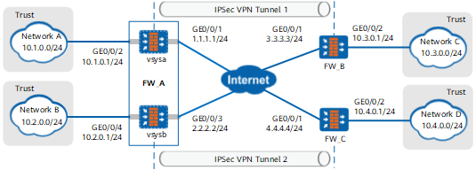
Data Planning
Item |
Data |
|
|---|---|---|
FW_A |
vsysa |
WAN interface: GE0/0/1 IP address of the WAN interface: 1.1.1.1/24 Security zone of the WAN interface: Untrust |
LAN interface: GE0/0/2 IP address of the LAN interface: 10.1.0.1/24 IP address range of the LAN interface: 10.1.0.0/24 Security zone of the LAN interface: Trust |
||
IPSec configuration Peer IP address: 3.3.3.3/24 Authentication mode: pre-shared key Pre-shared key: Admin@123 Local ID: IP address Peer ID: any |
||
vsysb |
WAN interface: GE0/0/3 IP address of the WAN interface: 2.2.2.2/24 Security zone of the WAN interface: Untrust |
|
LAN interface: GE0/0/4 IP address of the LAN interface: 10.2.0.1/24 IP address range of the LAN interface: 10.2.0.0/24 Security zone of the LAN interface: Trust |
||
IPSec configuration Peer IP address: 4.4.4.4/24 Authentication mode: pre-shared key Pre-shared key: Admin@123 Local ID: IP address Peer ID: any |
||
FW_B |
Interface: GE0/0/1 IP address: 3.3.3.3/24 Security zone of the interface: Untrust |
|
Interface: GE0/0/2 IP address: 10.3.0.1/24 IP address range of the LAN interface: 10.3.0.0/24 Security zone of the interface: Trust |
||
IPSec configuration Peer IP address: 1.1.1.1/24 Authentication mode: pre-shared key Pre-shared key: Admin@123 Local ID: IP address Peer ID: any |
||
FW_C |
Interface: GE0/0/1 IP address: 4.4.4.4/24 Security zone of the interface: Untrust |
|
Interface: GE0/0/2 IP address: 10.4.0.1/24 IP address range of the LAN interface: 10.4.0.0/24 Security zone of the interface: Trust |
||
IPSec configuration Peer IP address: 2.2.2.2/24 Authentication mode: pre-shared key Pre-shared key: Admin@123 Local ID: IP address Peer ID: any |
||
Configuration Roadmap

The configuration roadmap is the same in vsysa and vsysb, and on FW_B and FW_C. This section uses vsysa and FW_B as examples to describe how to configure virtual systems to establish IPSec VPN tunnels with the peer gateway using independent public IP addresses. For configurations of vsysb and FW_C, see those of vsysa and FW_B.
-
- In the root system, create virtual system vsysa and allocate resources to it.
- Complete basic configurations of interfaces, routes, and security policies in vsysa.
- Configure IPSec policies in vsysa, including basic IPSec policy information, data flow to be protected by IPSec, and negotiation parameters of security proposals.
-
- Complete basic interface configurations.
- Configure security policies to allow specific subnets to communicate.
- Configure a route to the peer virtual system.
- Configure IPSec policies, including basic IPSec policy information, data flow to be protected by IPSec, and negotiation parameters of security proposals.
Procedure
- Configure FW_A.
- Choose Dashboard from the main menu. In the Device Information pane, click Configure following the Virtual System option to enable the virtual system function.
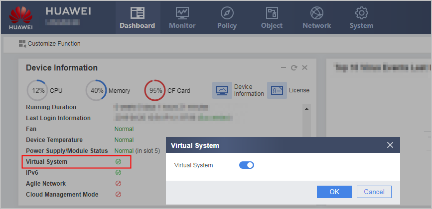
- Configure the virtual system resource class.
- Choose .
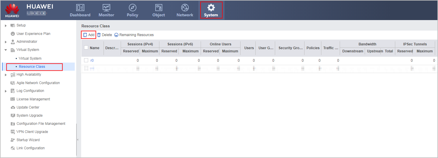
Click Add. In the displayed dialog box, create system resource class r1 in vsysa and set the reserved number and maximum number of IPSec tunnels, as shown in the following figure.
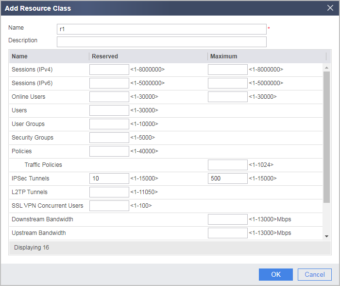
The reserved number of IPSec tunnels configured for a virtual system cannot be greater than the maximum number of IPSec tunnels.
- Choose .
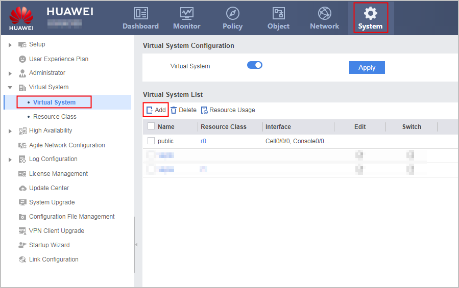
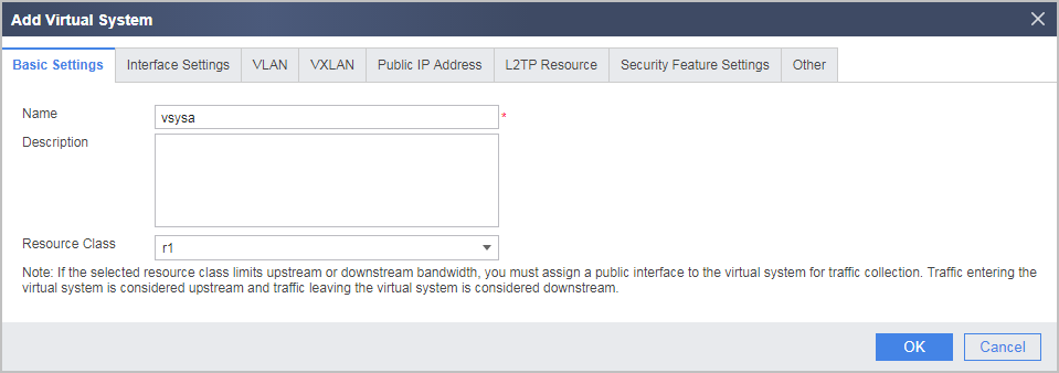
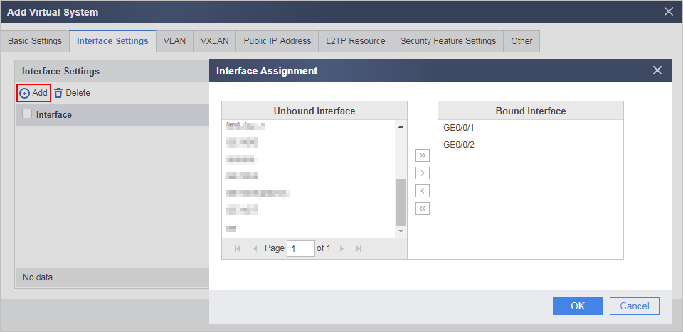
- In the root system, create virtual system vsysa and allocate resources to it.
- Configure interfaces in vsysa.
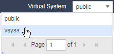
Select vsysa from the Virtual System drop-down list in the upper right corner to access vsysa.
- Choose .
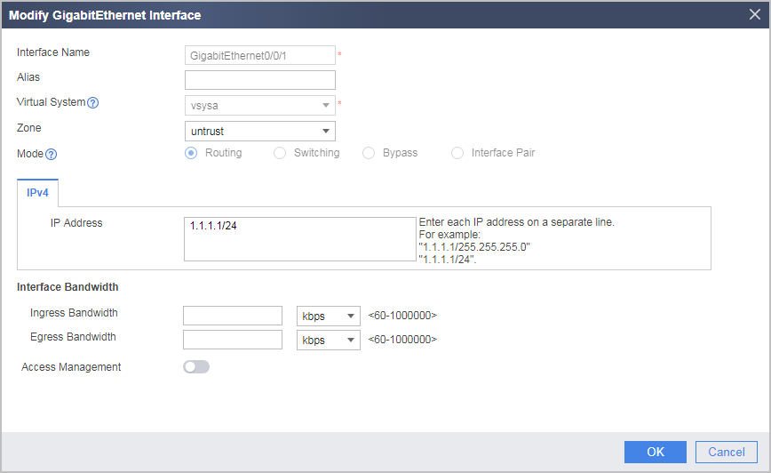
Click Edit following GE0/0/1. In the displayed dialog box, set the IP address and security zone, as shown in the following figure.
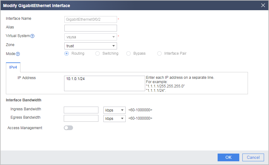
Click Edit following GE0/0/2. In the displayed dialog box, set the IP address and security zone, as shown in the following figure.
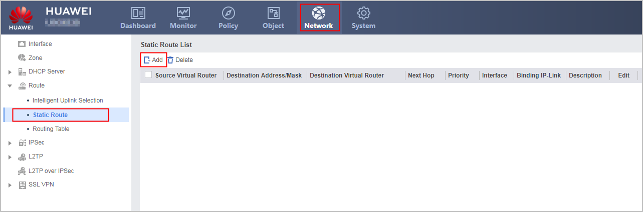
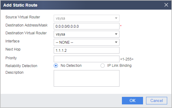
- Configure routes in vsysa. Assume that the next-hop IP address of the route from vsysa to the Internet is 1.1.1.2.
- Configure security policies in vsysa.
- Choose .
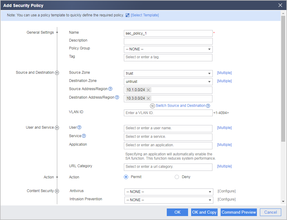
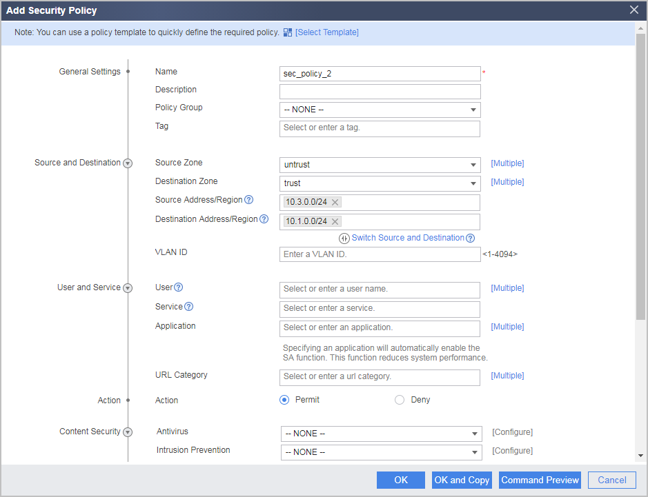
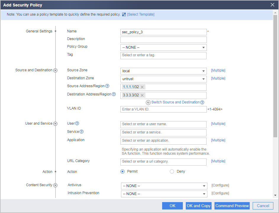
Click Add and select Add Security Policy. In the displayed dialog box, configure security policies as follows.
# Configure a security policy from the Trust zone to the Untrust zone.
# Configure a security policy from the Untrust zone to the Trust zone.
# Configure a security policy from the Local zone to the Untrust zone.
# Configure a security policy from the Untrust zone to the Local zone.
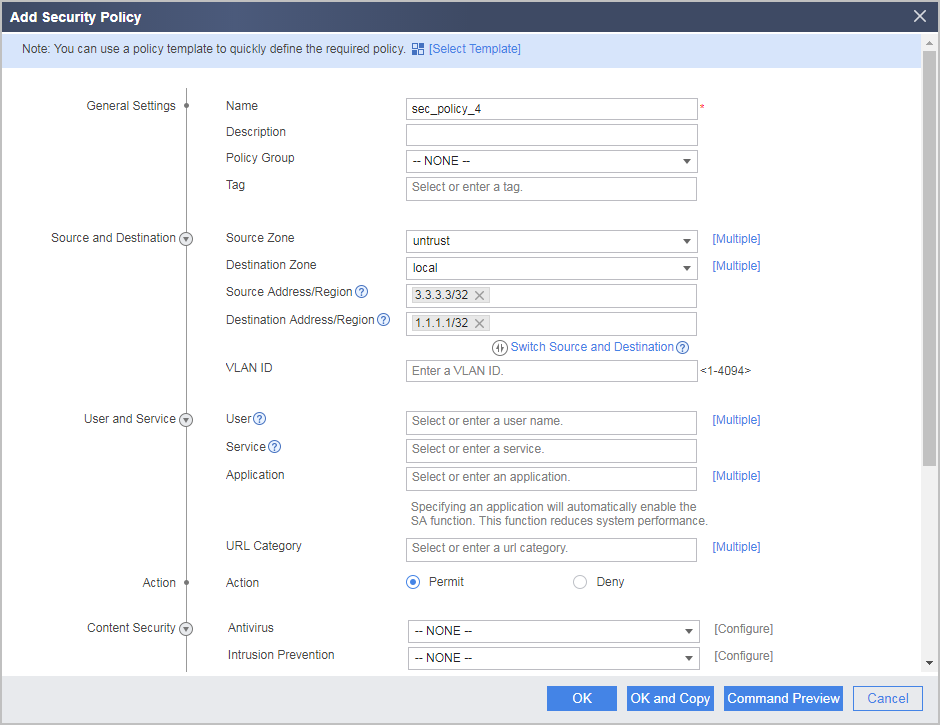
The local-untrust interzone policy controls whether IKE negotiation packets can pass through the FW. This policy can use the source and destination addresses, protocol, or port as the matching condition. In this example, the source and destination addresses are used as the matching condition. To use the protocol or port as the matching condition, you need to enable ESP and port 500 for UDP (port 4500 also in NAT traversal scenarios).
- Configure IPSec policies in vsysa.
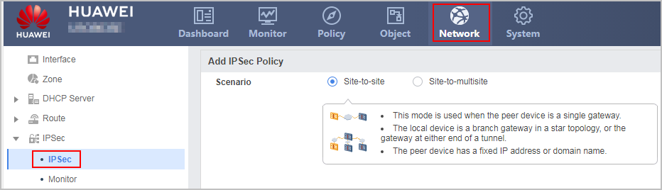
- Choose . Click Add and set Scenario to Site-to-site.
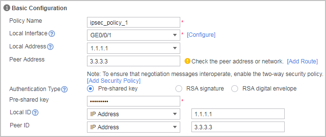
Configure the basic IPSec policy information, specify the remote gateway, and set the pre-shared key to Admin@123.
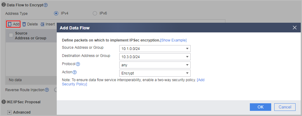
In Data Flow to Encrypt, click Add to add a data flow as follows.
Configure the security proposal.
Use the default parameters. To modify a parameter, click Advanced in IKE/IPSec Proposal. Security proposal configurations used on both ends of a tunnel must be the same.
- Click Apply.
- Choose . Click Add and set Scenario to Site-to-site.
- Choose Dashboard from the main menu. In the Device Information pane, click Configure following the Virtual System option to enable the virtual system function.
- Configure FW_B.
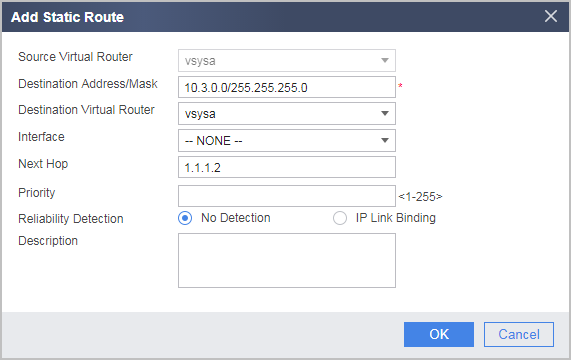
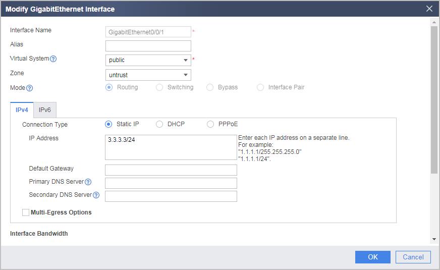
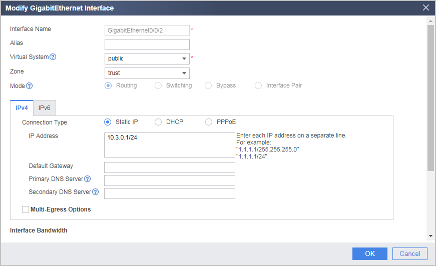
- Set interface IP addresses and assign the interfaces to security zones on FW_B.
- Configure security policies on FW_B to allow specific subnets to communicate.
- Choose .
Click Add and select Add Security Policy. In the displayed dialog box, configure security policies as follows.
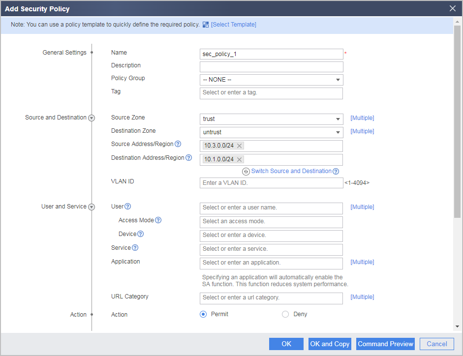
# Configure a security policy from the Trust zone to the Untrust zone.
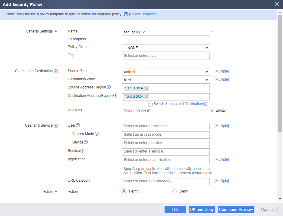
# Configure a security policy from the Untrust zone to the Trust zone.
# Configure a security policy from the Local zone to the Untrust zone.
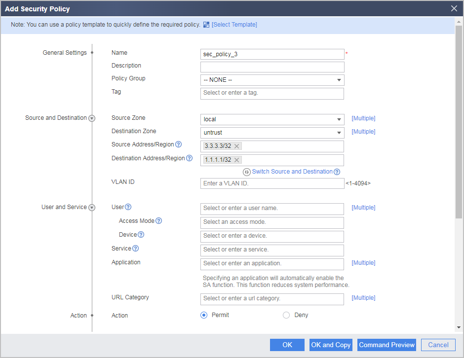
# Configure a security policy from the Untrust zone to the Local zone.
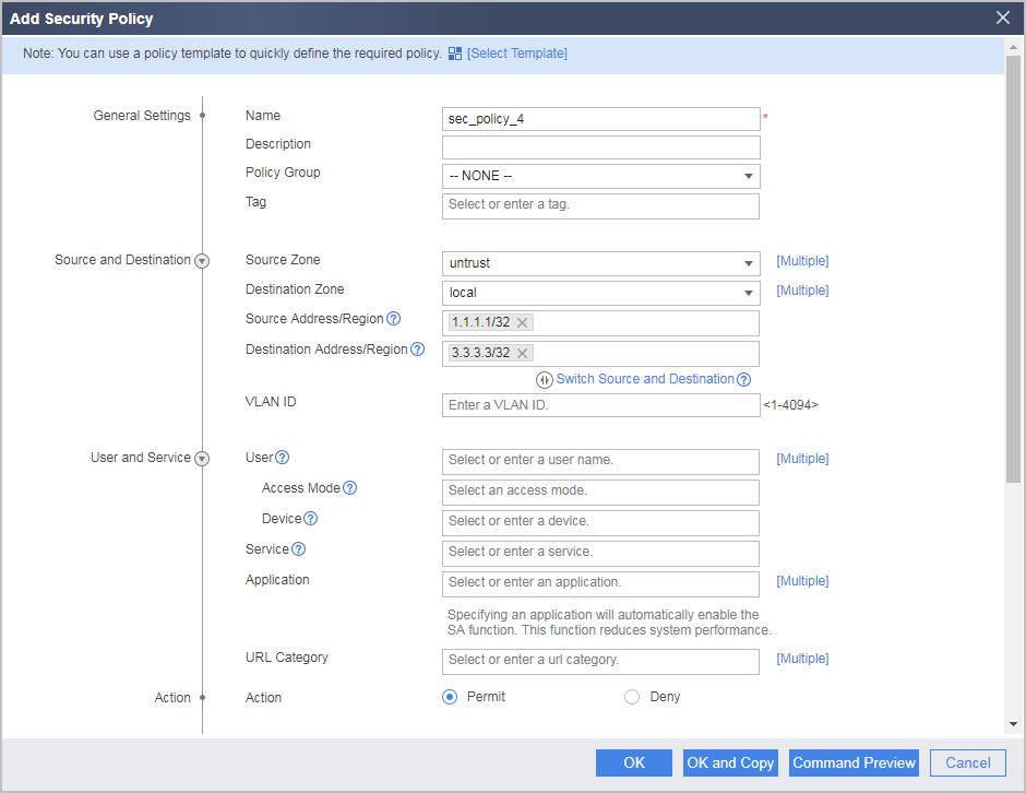
The local-untrust interzone policy controls whether IKE negotiation packets can pass through the FW. This policy can use the source and destination addresses, protocol, or port as the matching condition. In this example, the source and destination addresses are used as the matching condition. To use the protocol or port as the matching condition, you need to enable ESP and port 500 for UDP (port 4500 also in NAT traversal scenarios).
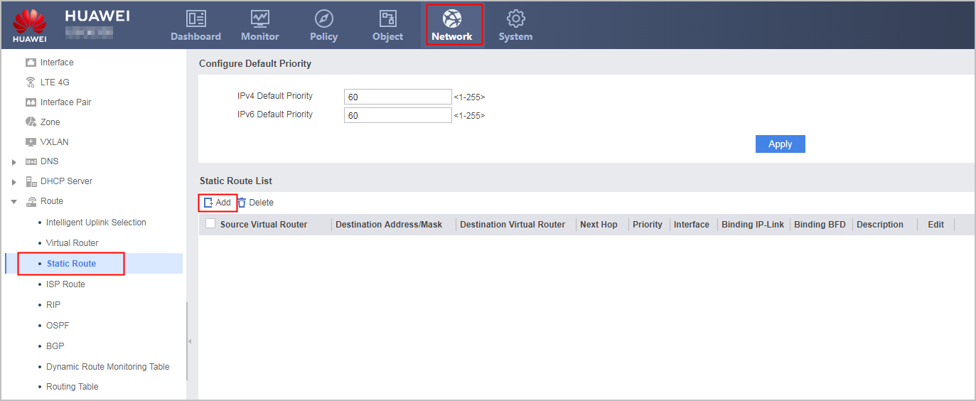
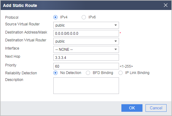
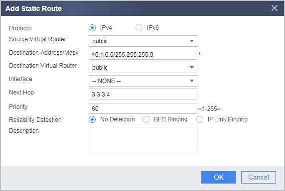
- Configure routes on FW_B. Assume that the next-hop IP address of the route from FW_B to the Internet is 3.3.3.4.
- Configure IPSec policies on FW_B.
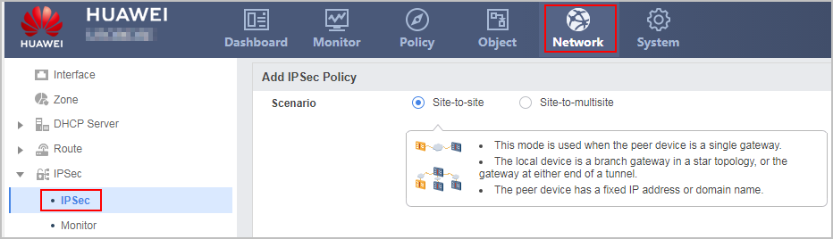
- Choose . Click Add and set Scenario to Site-to-site.
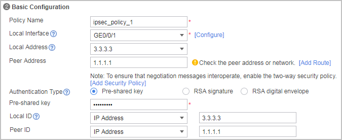
Configure the basic IPSec policy information, specify the remote gateway, and set the pre-shared key to Admin@123.
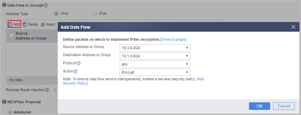
In Data Flow to Encrypt , click Add to add a data flow as follows.
Configure the security proposal.
Use the default parameters. To modify a parameter, click Advanced in IKE/IPSec Proposal. Security proposal configurations used on both ends of a tunnel must be the same.
- Click Apply.
- Choose . Click Add and set Scenario to Site-to-site.


Configuration Scripts
The configuration script of the root system on FW_A:
#
sysname FW_A
#
vsys enable
#
resource-class r1
 resource-item-limit ipsec-tunnel reserved-number 10 maximum 500
#
vsys name vsysa 1
 assign interface GigabitEthernet0/0/1
 assign interface GigabitEthernet0/0/2
 assign resource-class r1
#
vsys name vsysb 2
 assign interface GigabitEthernet0/0/3
 assign interface GigabitEthernet0/0/4
 assign resource-class r1
#
interface GigabitEthernet0/0/1
 ip binding vpn-instance vsysa
 ip address 1.1.1.1 255.255.255.0
 ipsec policy ipsec2412145818
#
interface GigabitEthernet0/0/2
 ip binding vpn-instance vsysa
 ip address 10.1.0.1 255.255.255.0
#
interface GigabitEthernet0/0/3
 ip binding vpn-instance vsysb
 ip address 2.2.2.2 255.255.255.0
 ipsec policy ipsec2412145817
#
interface GigabitEthernet0/0/4
 ip binding vpn-instance vsysb
 ip address 10.2.0.1 255.255.255.0
The configuration script of vsysa on FW_A:
#
switch vsys vsysa
#
acl number 3000
 rule 5 permit ip source 10.1.0.0 0.0.0.255 destination 10.3.0.0 0.0.0.255
#
ipsec proposal prop24121458179
 encapsulation-mode auto
 esp authentication-algorithm sha2-256
 esp encryption-algorithm aes-256
#
ike proposal 3
 encryption-algorithm aes-256
 dh group2
 authentication-algorithm sha2-256
 authentication-method pre-share
 integrity-algorithm hmac-sha2-256
 prf hmac-sha2-256
#
ike peer ike241214581790
 exchange-mode auto
 pre-shared-key %^%#m`wdHMo4eVMY2&*+hDV~BbN&<=zoQ@d{n%=**qR6%^%#
 ike-proposal 3
 remote-id-type ip
 remote-id 3.3.3.3
 local-id 1.1.1.1
 remote-address 3.3.3.3
#
ipsec policy ipsec2412145818 1 isakmp
 security acl 3000
 ike-peer ike241214581790
 proposal prop24121458179
 tunnel local applied-interface
 alias ipsec_policy_1
 sa trigger-mode auto
 sa duration traffic-based 20971520
 sa duration time-based 3600
#
interface GigabitEthernet0/0/1
 ip binding vpn-instance vsysa
 ip address 1.1.1.1 255.255.255.0
 set public-interface
 ipsec policy ipsec2412145818
#
interface GigabitEthernet0/0/2
 ip binding vpn-instance vsysa
 ip address 10.1.0.1 255.255.255.0
#
firewall zone trust
 set priority 85
 add interface GigabitEthernet0/0/2
#
firewall zone untrust
 set priority 5
 add interface GigabitEthernet0/0/1
#
security-policy
 rule name sec_policy_1
  source-zone trust
  destination-zone untrust
  source-address 10.1.0.0 mask 255.255.255.0
  destination-address 10.3.0.0 mask 255.255.255.0
  action permit
 rule name sec_policy_2
  source-zone untrust
  destination-zone trust
  source-address 10.3.0.0 mask 255.255.255.0
  destination-address 10.1.0.0 mask 255.255.255.0
  action permit
 rule name sec_policy_3
  source-zone local
  destination-zone untrust
  source-address 1.1.1.1 mask 255.255.255.255
  destination-address 3.3.3.3 mask 255.255.255.255
  action permit
 rule name sec_policy_4
  source-zone untrust
  destination-zone local
  source-address 3.3.3.3 mask 255.255.255.255
  destination-address 1.1.1.1 mask 255.255.255.255
  action permit
#
ip route-static 0.0.0.0 0.0.0.0 1.1.1.2
ip route-static 10.3.0.0 255.255.255.0 1.1.1.2
#
return
The configuration script of vsysb on FW_A:
#
switch vsys vsysb
#
acl number 3001
 rule 5 permit ip source 10.2.0.0 0.0.0.255 destination 10.4.0.0 0.0.0.255
#
ipsec proposal prop24121458178
 encapsulation-mode auto
 esp authentication-algorithm sha2-256
 esp encryption-algorithm aes-256
#
ike proposal 4
 encryption-algorithm aes-256
 dh group2
 authentication-algorithm sha2-256
 authentication-method pre-share
 integrity-algorithm hmac-sha2-256
 prf hmac-sha2-256
#
ike peer ike241214581791
 exchange-mode auto
 pre-shared-key %^%#m`wdHMo4eVMY2&*+hDV~BbN&<=zoQ@d{n%=**qR6%^%#
 ike-proposal 4
 remote-id-type ip
 remote-id 4.4.4.4
 local-id 2.2.2.2
 remote-address 4.4.4.4
#
ipsec policy ipsec2412145817 1 isakmp
 security acl 3001
 ike-peer ike241214581791
 proposal prop24121458178
 tunnel local applied-interface
 alias ipsec_policy_2
 sa trigger-mode auto
 sa duration traffic-based 20971520
 sa duration time-based 3600
#
interface GigabitEthernet0/0/3
 ip binding vpn-instance vsysb
 ip address 2.2.2.2 255.255.255.0
 set public-interface
 ipsec policy ipsec2412145817
#
interface GigabitEthernet0/0/4
 ip binding vpn-instance vsysb
 ip address 10.2.0.1 255.255.255.0
#
firewall zone trust
 set priority 85
 add interface GigabitEthernet0/0/4
#
firewall zone untrust
 set priority 5
 add interface GigabitEthernet0/0/3
#
security-policy
 rule name sec_policy_1
  source-zone trust
  destination-zone untrust
  source-address 10.2.0.0 mask 255.255.255.0
  destination-address 10.4.0.0 mask 255.255.255.0
  action permit
 rule name sec_policy_2
  source-zone untrust
  destination-zone trust
  source-address 10.4.0.0 mask 255.255.255.0
  destination-address 10.2.0.0 mask 255.255.255.0
  action permit
 rule name sec_policy_3
  source-zone local
  destination-zone untrust
  source-address 2.2.2.2 mask 255.255.255.255
  destination-address 4.4.4.4 mask 255.255.255.255
  action permit
 rule name sec_policy_4
  source-zone untrust
  destination-zone local
  source-address 4.4.4.4 mask 255.255.255.255
  destination-address 2.2.2.2 mask 255.255.255.255
  action permit
#
ip route-static 0.0.0.0 0.0.0.0 2.2.2.3
ip route-static 10.4.0.0 255.255.255.0 2.2.2.3
#
return
The configuration script on FW_B:
#
sysname FW_B
#
acl number 3000
 rule 5 permit ip source 10.3.0.0 0.0.0.255 destination 10.1.0.0 0.0.0.255
#
ipsec proposal prop24121543361
 encapsulation-mode auto
 esp authentication-algorithm sha2-256
 esp encryption-algorithm aes-256
#
ike proposal 1
 encryption-algorithm aes-256
 dh group2
 authentication-algorithm sha2-256
 authentication-method pre-share
 integrity-algorithm hmac-sha2-256
 prf hmac-sha2-256
#
ike peer ike241215433617
 exchange-mode auto
 pre-shared-key %^%#@ama1^ws3/PX+B.f~tnNDy(q~gjoR%dmP6.\U#5~%^%#
 ike-proposal 1
 remote-id-type ip
 remote-id 1.1.1.1
 local-id 3.3.3.3
 remote-address 1.1.1.1
#
ipsec policy ipsec2412154336 1 isakmp
 security acl 3000
 ike-peer ike241215433617
 proposal prop24121543361
 tunnel local applied-interface
 alias ipsec_policy_1
 sa trigger-mode auto
 sa duration traffic-based 5242880
 sa duration time-based 3600
#
interface GigabitEthernet0/0/1
 ip address 3.3.3.3 255.255.255.0
 set public-interface
 ipsec policy ipsec2412154336
#
interface GigabitEthernet0/0/2
 ip address 10.3.0.1 255.255.255.0
#
firewall zone trust
 set priority 85
 add interface GigabitEthernet0/0/2
#
firewall zone untrust
 set priority 5
 add interface GigabitEthernet0/0/1
#
ip route-static 0.0.0.0 0.0.0.0 3.3.3.4
ip route-static 10.1.0.0 255.255.255.0 3.3.3.4
#
security-policy
 rule name sec_policy_1
  source-zone trust
  destination-zone untrust
  source-address 10.3.0.0 mask 255.255.255.0
  destination-address 10.1.0.0 mask 255.255.255.0
  action permit
 rule name sec_policy_2
  source-zone untrust
  destination-zone trust
  source-address 10.1.0.0 mask 255.255.255.0
  destination-address 10.3.0.0 mask 255.255.255.0
  action permit
 rule name sec_policy_3
  source-zone local
  destination-zone untrust
  source-address 3.3.3.3 mask 255.255.255.255
  destination-address 1.1.1.1 mask 255.255.255.255
  action permit
 rule name sec_policy_4
  source-zone untrust
  destination-zone local
  source-address 1.1.1.1 mask 255.255.255.255
  destination-address 3.3.3.3 mask 255.255.255.255
  action permit
The configuration script on FW_C:
#
sysname FW_C
#
acl number 3000
 rule 5 permit ip source 10.4.0.0 0.0.0.255 destination 10.2.0.0 0.0.0.255
#
ipsec proposal prop24121543361
 encapsulation-mode auto
 esp authentication-algorithm sha2-256
 esp encryption-algorithm aes-256
#
ike proposal 1
 encryption-algorithm aes-256
 dh group2
 authentication-algorithm sha2-256
 authentication-method pre-share
 integrity-algorithm hmac-sha2-256
 prf hmac-sha2-256
#
ike peer ike241215433617
 exchange-mode auto
 pre-shared-key %^%#@ama1^ws3/PX+B.f~tnNDy(q~gjoR%dmP6.\U#5~%^%#
 ike-proposal 1
 remote-id-type ip
 remote-id 2.2.2.2
 local-id 4.4.4.4
 remote-address 2.2.2.2
#
ipsec policy ipsec2412154336 1 isakmp
 security acl 3000
 ike-peer ike241215433617
 proposal prop24121543361
 tunnel local applied-interface
 alias ipsec_policy_1
 sa trigger-mode auto
 sa duration traffic-based 5242880
 sa duration time-based 3600
#
interface GigabitEthernet0/0/1
 ip address 4.4.4.4 255.255.255.0
 set public-interface
 ipsec policy ipsec2412154336
#
interface GigabitEthernet0/0/2
 ip address 10.4.0.1 255.255.255.0
#
firewall zone trust
 set priority 85
 add interface GigabitEthernet0/0/2
#
firewall zone untrust
 set priority 5
 add interface GigabitEthernet0/0/1
#
ip route-static 0.0.0.0 0.0.0.0 4.4.4.5
ip route-static 10.1.0.0 255.255.255.0 4.4.4.5
#
security-policy
 rule name sec_policy_1
  source-zone trust
  destination-zone untrust
  source-address 10.4.0.0 mask 255.255.255.0
  destination-address 10.2.0.0 mask 255.255.255.0
  action permit
 rule name sec_policy_2
  source-zone untrust
  destination-zone trust
  source-address 10.2.0.0 mask 255.255.255.0
  destination-address 10.4.0.0 mask 255.255.255.0
  action permit
 rule name sec_policy_3
  source-zone local
  destination-zone untrust
  source-address 4.4.4.4 mask 255.255.255.255
  destination-address 2.2.2.2 mask 255.255.255.255
  action permit
 rule name sec_policy_4
  source-zone untrust
  destination-zone local
  source-address 2.2.2.2 mask 255.255.255.255
  destination-address 4.4.4.4 mask 255.255.255.255
  action permit