< Home

CLI: Example for Configuring L2TP VPN (Local Authentication) in the Call-LNS Scenario

This section provides an example for configuring L2TP VPN (local authentication) in the call-LNS scenario. In the scenario, the LAC and LNS establish a permanent L2TP VPN tunnel. Employees in the branch can access headquarters servers through the L2TP VPN tunnel.

Networking Requirements

As shown in Figure 1, the egress gateway of the branch is the LAC, and the egress gateway of the headquarters is the LNS. Employees in the branch need to access headquarters servers across the Internet. The enterprise needs to establish an L2TP VPN tunnel between the LAC and LNS so that employees in the branch can access headquarters servers through the L2TP VPN tunnel.
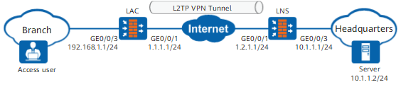
Figure 1 Networking diagram for configuring L2TP VPN in the call-LNS scenario

Data Planning

Item

Data

LAC

Interface

Interface ID: GigabitEthernet 0/0/1

IP address: 1.1.1.1/24

Security zone: Untrust

Interface ID: GigabitEthernet 0/0/3

IP address: 192.168.1.1/24

Security zone: Trust

L2TP configuration

Server address configuration mode: IP address

Server address: 1.2.1.1/24

LAC automatic dialup: enabled

User name: user0001

Password: Password123

Local tunnel name: LAC

Tunnel authentication password: Hello123

LNS

Interface

Interface ID: GigabitEthernet 0/0/1

IP address: 1.2.1.1/24

Security zone: Untrust

Interface ID: GigabitEthernet 0/0/3

IP address: 10.1.1.1/24

Security zone: Trust

L2TP configuration

Peer tunnel name: LAC

Tunnel authentication password: Hello123

User authentication name: user0001

Password: Password123

Server address: 10.2.1.1/24

User address pool: 10.2.1.2/24 to 10.2.1.100/24

NOTE:

If the intranet server IP address and address pool addresses are on different network segments, configure a route on the intranet server to an address in the address pool.

Procedure

  • Configure the LAC.
    1. Configure IP addresses for interfaces and assign the interfaces to security zones.

      <sysname> system-view
      [sysname] sysname LAC
      [LAC] interface GigabitEthernet 0/0/1 
      [LAC-GigabitEthernet0/0/1] ip address 1.1.1.1 24 
      [LAC-GigabitEthernet0/0/1] quit
      [LAC] firewall zone untrust
      [LAC-zone-untrust] add interface GigabitEthernet 0/0/1
      [LAC-zone-untrust] quit
      [LAC] interface GigabitEthernet 0/0/3 
      [LAC-GigabitEthernet0/0/3] ip address 192.168.1.1 24 
      [LAC-GigabitEthernet0/0/3] quit
      [LAC] firewall zone trust
      [LAC-zone-trust] add interface GigabitEthernet 0/0/3
      [LAC-zone-trust] quit

    2. Configure L2TP.

      If the LAC needs to establish L2TP VPN tunnels with multiple LNSs, specify multiple LNS IP addresses in the start l2tp command.

      [LAC] l2tp enable
      [LAC] l2tp-group 1
      [LAC-l2tp-1] tunnel name LAC
      [LAC-l2tp-1] start l2tp ip 1.2.1.1 fullusername user0001
      [LAC-l2tp-1] tunnel authentication
      [LAC-l2tp-1] tunnel password cipher Hello123
      [LAC-l2tp-1] quit

    3. Configure a VT interface.

      [LAC] interface Virtual-Template 1
      [LAC-Virtual-Template1] ppp authentication-mode chap
       The command is used to configure the PPP authentication mode on the local end. Confirm that the peer end adopts the corresponding PPP
       authentication. Continue[Y/N]:y
      [LAC-Virtual-Template1] ppp chap user user0001
      [LAC-Virtual-Template1] ppp chap password cipher Password123
      [LAC-Virtual-Template1] ip address ppp-negotiate
      [LAC-Virtual-Template1] call-lns local-user user0001
      [LAC-Virtual-Template1] quit
      [LAC] firewall zone dmz
      [LAC-zone-dmz] add interface Virtual-Template 1 
      [LAC-zone-dmz] quit

    4. Configure routes.

      1. Configure a route to headquarters servers and set the outbound interface of the route to the LAC VT interface.
        [LAC] ip route-static 10.1.1.0 24 Virtual-Template 1
      2. Configure a route to the Internet. It is assumed that the next-hop address of the route from the LAC to the Internet is 1.1.1.2.
        [LAC] ip route-static 0.0.0.0 0.0.0.0 1.1.1.2

    5. Configure an outbound interface-based source NAT policy.

      After the LAC dials up successfully, the LNS generates a route, with both the destination address and next-hop address being the IP address (allocated by the LNS from the address pool) of the LAC VT interface. The traffic sent by the LNS travels along this route to the L2TP tunnel. Therefore, the source IP addresses of packets sent by the LAC must be translated to the IP address of the LAC VT interface before they reach the LNS, so that the traffic sent by the LNS can be routed correctly. If source NAT is not implemented, services will be interrupted.

      [LAC] nat-policy
      [LAC-policy-nat] rule name p1
      [LAC-policy-nat-rule-p1] source-zone trust
      [LAC-policy-nat-rule-p1] egress-interface Virtual-Template 1
      [LAC-policy-nat-rule-p1] source-address 192.168.1.0 24
      [LAC-policy-nat-rule-p1] action source-nat easy-ip
      [LAC-policy-nat-rule-p1] quit
      [LAC-policy-nat] quit

    6. Configure interzone security policies on the LAC.

      # Configure an interzone security policy between the Trust zone and DMZ to permit the traffic sent by employees in the branch to access the intranet of the headquarters and the traffic sent by devices on the intranet of the headquarters to the employees.

      [LAC] security-policy
      [LAC-policy-security] rule name service_td
      [LAC-policy-security-rule-service_td] source-zone trust
      [LAC-policy-security-rule-service_td] destination-zone dmz
      [LAC-policy-security-rule-service_td] source-address 192.168.1.0 24
      [LAC-policy-security-rule-service_td] destination-address 10.1.1.0 24
      [LAC-policy-security-rule-service_td] action permit
      [LAC-policy-security-rule-service_td] quit
      [LAC-policy-security] rule name service_dt
      [LAC-policy-security-rule-service_dt] source-zone dmz
      [LAC-policy-security-rule-service_dt] destination-zone trust
      [LAC-policy-security-rule-service_dt] source-address 10.1.1.0 24
      [LAC-policy-security-rule-service_dt] destination-address 192.168.1.0 24
      [LAC-policy-security-rule-service_dt] action permit
      [LAC-policy-security-rule-service_dt] quit

      # Configure an interzone security policy from the Local zone to the Untrust zone to permit L2TP packets.

      [LAC-policy-security] rule name l2tp_lu
      [LAC-policy-security-rule-l2tp_lu] source-zone local
      [LAC-policy-security-rule-l2tp_lu] destination-zone untrust
      [LAC-policy-security-rule-l2tp_lu] source-address 1.1.1.0 24
      [LAC-policy-security-rule-l2tp_lu] destination-address 1.2.1.0 24
      [LAC-policy-security-rule-l2tp_lu] action permit
      [LAC-policy-security-rule-l2tp_lu] quit

  • Configure the LNS.
    1. Configure IP addresses for interfaces and assign the interfaces to security zones.

      <LNS> system-view
      [LNS] sysname LNS
      [LNS] interface GigabitEthernet 0/0/1 
      [LNS-GigabitEthernet0/0/1] ip address 1.2.1.1 24 
      [LNS-GigabitEthernet0/0/1] quit
      [LNS] firewall zone untrust
      [LNS-zone-untrust] add interface GigabitEthernet 0/0/1
      [LNS-zone-untrust] quit
      [LNS] interface GigabitEthernet 0/0/3 
      [LNS-GigabitEthernet0/0/3] ip address 10.1.1.1 24 
      [LNS-GigabitEthernet0/0/3] quit
      [LNS] firewall zone trust
      [LNS-zone-trust] add interface GigabitEthernet 0/0/3
      [LNS-zone-trust] quit

    2. Configure an address pool.

      If the actual address pool addresses and headquarters addresses reside on the same network segment, you must enable the proxy ARP function on the LNS interface connecting to the headquarters to ensure that the LNS can respond to the ARP requests from the servers at the headquarters.

      [LNS] ip pool pool
      [LNS-ip-pool-pool] section 1 10.2.1.2 10.2.1.100
      [LNS-ip-pool-pool] quit

    3. Configure a service scheme.

      [LNS] aaa
      [LNS-aaa] service-scheme l2tp 
      [LNS-aaa-service-l2tp] ip-pool pool
      [LNS-aaa-service-l2tp] quit 
      

    4. Configure the authentication domain and user information.

      1. Configure the authentication domain.

        To implement user name-based policy control on L2TP access users, you must specify the internetaccess parameter.

        [LNS-aaa] domain default
        [LNS-aaa-domain-default] service-type l2tp
      2. Configure a branch user and the user group of the user.
        [LNS] user-manage group /default/branch
        [LNS-usergroup-/default/branch] quit
        [LNS] user-manage user user0001
        [LNS-localuser-user0001] alias branch
        [LNS-localuser-user0001] parent-group /default/branch
        [LNS-localuser-user0001] password Password123
        [LNS-localuser-user0001] quit

    5. Configure a VT interface.

      [LNS] interface Virtual-Template 1
      [LNS-Virtual-Template1] ip address 10.2.1.1 24
      [LNS-Virtual-Template1] ppp authentication-mode chap
      [LNS-Virtual-Template1] remote service-scheme l2tp
      [LNS-Virtual-Template1] quit
      [LNS] firewall zone dmz
      [LNS-zone-dmz] add interface Virtual-Template 1
      [LNS-zone-dmz] quit

    6. Configure an L2TP group.

      [LNS] l2tp enable
      [LNS] l2tp-group 2
      [LNS-l2tp-2] allow l2tp virtual-template 1 remote LAC
      [LNS-l2tp-2] tunnel authentication
      [LNS-l2tp-2] tunnel password cipher Hello123
      [LNS-l2tp-2] quit

    7. Configure a route to the Internet. It is assumed that the next-hop address of the route from the LNS to the Internet is 1.2.1.2.

      [LNS] ip route-static 0.0.0.0 0.0.0.0 1.2.1.2

    8. Configure interzone security policies on the LNS.

      # Configure an interzone security policy between the Trust zone and DMZ to permit the traffic sent by employees in the branch to access the intranet of the headquarters and the traffic sent by devices on the intranet of the headquarters to the employees.

      [LNS] security-policy
      [LNS-policy-security] rule name service_td
      [LNS-policy-security-rule-service_td] source-zone trust
      [LNS-policy-security-rule-service_td] destination-zone dmz
      [LNS-policy-security-rule-service_td] source-address 10.1.1.0 24
      [LNS-policy-security-rule-service_td] destination-address 10.2.1.0 24
      [LNS-policy-security-rule-service_td] action permit
      [LNS-policy-security-rule-service_td] quit
      [LNS-policy-security] rule name service_dt
      [LNS-policy-security-rule-service_dt] source-zone dmz
      [LNS-policy-security-rule-service_dt] destination-zone trust
      [LNS-policy-security-rule-service_dt] source-address 10.2.1.0 24
      [LNS-policy-security-rule-service_dt] destination-address 10.1.1.0 24
      [LNS-policy-security-rule-service_dt] action permit
      [LNS-policy-security-rule-service_dt] quit

      # Configure an interzone security policy from the Untrust zone to the Local zone to permit L2TP packets.

      [LNS-policy-security] rule name l2tp_ul
      [LNS-policy-security-rule-l2tp_ul] source-zone untrust
      [LNS-policy-security-rule-l2tp_ul] destination-zone local
      [LNS-policy-security-rule-l2tp_ul] source-address 1.1.1.0 24
      [LNS-policy-security-rule-l2tp_ul] destination-address 1.2.1.0 24
      [LNS-policy-security-rule-l2tp_ul] action permit
      [LNS-policy-security-rule-l2tp_ul] quit

Verification

  1. Configure the PC of the branch employee to ping a headquarters server.
  2. Check L2TP tunnel establishment information on the LNS and LAC. The command output on the LNS is used as an example.

    1. Run the display l2tp tunnel command to check L2TP tunnel information. According to the command output, an L2TP tunnel is established successfully.
      [LNS] display l2tp tunnel
      L2TP::Total Tunnel: 1 
                            
       LocalTID RemoteTID RemoteAddress    Port   Sessions RemoteName  VpnInstance   
       ------------------------------------------------------------------------------
       2        1         1.1.1.1          61535   1         LAC                   
       ------------------------------------------------------------------------------
        Total 1, 1 printed           
    2. Run the display l2tp session command to check L2TP session information. According to the command output, an L2TP session is established successfully.

      [LNS] display l2tp session
      L2TP::Total Session: 1
                            
        LocalSID  RemoteSID  LocalTID   RemoteTID  UserID  UserName    VpnInstance   
       ------------------------------------------------------------------------------
        119       32         2           1          9689   user0001                     
       ------------------------------------------------------------------------------
        Total 1, 1 printed 

Configuration Scripts

  • Configuration script of the LAC

    #
     l2tp enable
     l2tp domain suffix-separator @
    #
    l2tp-group 1
     tunnel password cipher %$%$Sd2\*,\eT=XIuj1J`j36~K)_%$%$
     tunnel name LAC
     start l2tp ip 1.2.1.1 fullusername user0001
    #
    interface Virtual-Template1
     ppp authentication-mode chap
     ppp chap user user0001  
     ppp chap password cipher %$%$>x{UJZIoJ>`<}u"b0!#%\pg^%$%$
     ip address ppp-negotiate
     call-lns local-user user0001
    #
    interface GigabitEthernet0/0/1
     ip address 1.1.1.1 255.255.255.0
    #
    interface GigabitEthernet0/0/3
     ip address 192.168.1.1 255.255.255.0
    #
    firewall zone trust
     set priority 85
     add interface GigabitEthernet0/0/3
    #
    firewall zone untrust
     set priority 5 
     add interface GigabitEthernet0/0/1
    # 
    firewall zone dmz
     set priority 50
     add interface Virtual-Template1
    #
     ip route-static 10.1.1.0 255.255.255.0 Virtual-Template1
     ip route-static 0.0.0.0 0.0.0.0 1.1.1.2
    #
    nat-policy
     rule name p1
      source-zone trust
      egress-interface Virtual-Template1
      source-address 192.168.1.0 24
      action source-nat easy-ip
    #
    security-policy
      rule name service_td
        source-zone trust
        destination-zone dmz
        source-address 192.168.1.0 24
        destination-address 10.1.1.0 24
        action permit
      rule name service_dt
        source-zone dmz
        destination-zone trust
        source-address 10.1.1.0 24
        destination-address 192.168.1.0 24
         action permit
      rule name l2tp_lu
        source-zone local
        destination-zone untrust
        source-address 1.1.1.0 24
        destination-address 1.2.1.0 24
        action permit
    
  • Configuration script of the LNS

    #
    l2tp enable
    l2tp domain suffix-separator @
    #
    ip pool pool
     section 1 10.2.1.2 10.2.1.100
    #
    aaa  
     authentication-scheme default
    #
     authorization-scheme default
    #
    accounting-scheme default
    # 
     service-scheme l2tp
      ip-pool pool
    #
     domain default
      service-type l2tp
    #
    l2tp-group 2
     allow l2tp virtual-template 1 remote LAC
     tunnel password cipher %$%$cgc'GPcWL#hp3EC;K[nM[QH~%$%$
    #
    interface Virtual-Template1
     ppp authentication-mode chap
     remote service-scheme l2tp
     ip address 10.2.1.1 255.255.255.0
    #
    interface GigabitEthernet0/0/1
     ip address 1.2.1.1 255.255.255.0
    #
    interface GigabitEthernet0/0/3
     ip address 10.1.1.1 255.255.255.0
    #
    firewall zone trust
     set priority 85
     add interface GigabitEthernet0/0/3
    #
    firewall zone untrust
     set priority 5 
     add interface GigabitEthernet0/0/1
    # 
    firewall zone dmz
     set priority 50
     add interface Virtual-Template1
    #
     ip route-static 0.0.0.0 0.0.0.0 1.2.1.2
    #
    security-policy
      rule name service_td
        source-zone trust
        destination-zone dmz
        source-address 10.1.1.0 24
        destination-address 10.2.1.0 24
        action permit
      rule name service_dt
        source-zone dmz
        destination-zone trust
        source-address 10.2.1.0 24
        destination-address 10.1.1.0 24
        action permit
      rule name l2tp_ul
        source-zone untrust
        destination-zone local
        source-address 1.1.1.0 24
        destination-address 1.2.1.0 24
        action permit
    # The following configurations for creating users are stored in the database, not described in the configuration file.
    user-manage user user0001
     parent-group /default
     password **********
     undo multi-ip online enable
    
Copyright © Huawei Technologies Co., Ltd.
< Previous topic Next topic >
