CLI: Example for Configuring L2TP VPN (Local Authentication) in Cross-VPN Instance Scenarios
This section provides an example for configuring L2TP VPN in cross-VPN instance scenarios.
Networking Requirements
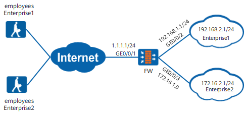
Enterprise1 and Enterprise2 need to share one LNS to provide L2TP remote access services for mobile employees, as shown in Figure 1.
Configuration Roadmap
- The LNS uses GigabitEthernet0/0/2 to connect Enterprise1 and GigabitEthernet0/0/3 to connect Enterprise2. To prevent the enterprise networks from affecting one another, bind the two interfaces to different VPN instances.
- Configure separate L2TP tunnels for each enterprise. For example, two virtual interface templates and two L2TP groups must be created. The virtual interfaces need to forward traffic to the enterprises in different VPN instances. Therefore, the virtual interface templates must be bound to different VPN instances.
Procedure
- Configure VPN instances, interfaces, security zones, and interzone security policies on the LNS.
- Configure mobile user information.
- Configure address pools and authentication domains.
- Configure address pools.
Address pools are used to assign private IP addresses to mobile employees. You need to configure two address pools for the enterprises to assign IP addresses to their mobile employees.
[LNS] ip pool enterprise1_pool
[LNS-ip-pool-enterprise1_pool] section 1 10.1.1.2 10.1.1.100
[LNS-ip-pool-enterprise1_pool] quit
[LNS] ip pool enterprise2_pool
[LNS-ip-pool-enterprise2_pool] section 1 10.1.2.2 10.1.2.100
[LNS-ip-pool-enterprise2_pool] quit

A route to the address pool must be configured on the intranet server.
- Configure the authentication domain.
Configure the service scheme used by access users.
[LNS] aaa
[LNS-aaa] service-scheme scheme1
[LNS-aaa-service-scheme1] ip-pool enterprise1_pool
[LNS-aaa-service-scheme1] quit
[LNS] aaa
[LNS-aaa] service-scheme scheme2
[LNS-aaa-service-scheme2] ip-pool enterprise2_pool
[LNS-aaa-service-scheme2] quit
Set the user access type in the authentication domain.
[LNS-aaa] domain domain1
[LNS-aaa-domain-domain1] service-type l2tp
[LNS-aaa-domain-domain1] quit
[LNS-aaa] domain domain2
[LNS-aaa-domain-domain2] service-type l2tp
[LNS-aaa-domain-domain2] quit
To implement user name-based policy control on VPN access users, you must specify the internetaccess parameter.
- Configure address pools.
- Configure VT interfaces.
- Configure an L2TP group.
- Configure routes on the LNS.
- Configure a route between the LNS and mobile employees.
- Since both the LNS and mobile employees are accessible to the Internet, the public route between them is already reachable. Therefore, you do not need to configure the route.
- When the LNS assigns IP addresses for mobile employees, it also pushes information about the route to the enterprise intranet. Therefore, you do not need to configure the route to the enterprise network on the devices used by mobile employees.
- Configure a route from the LNS to the enterprise intranet.
[LNS] ip route-static 192.168.2.0 24 vpn-instance vpn1 192.168.1.2
[LNS] ip route-static 172.16.2.0 24 vpn-instance vpn2 172.16.1.2
- Configure a route between the LNS and mobile employees.
- Configure interzone security policies on the LNS.
- Configure the SecoClient at the mobile user side.
- Open the SecoClient and access the home page.
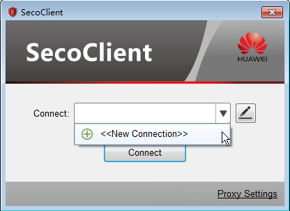
Select New Connection from the Connect drop-down list.
- Set L2TP VPN connection parameters.
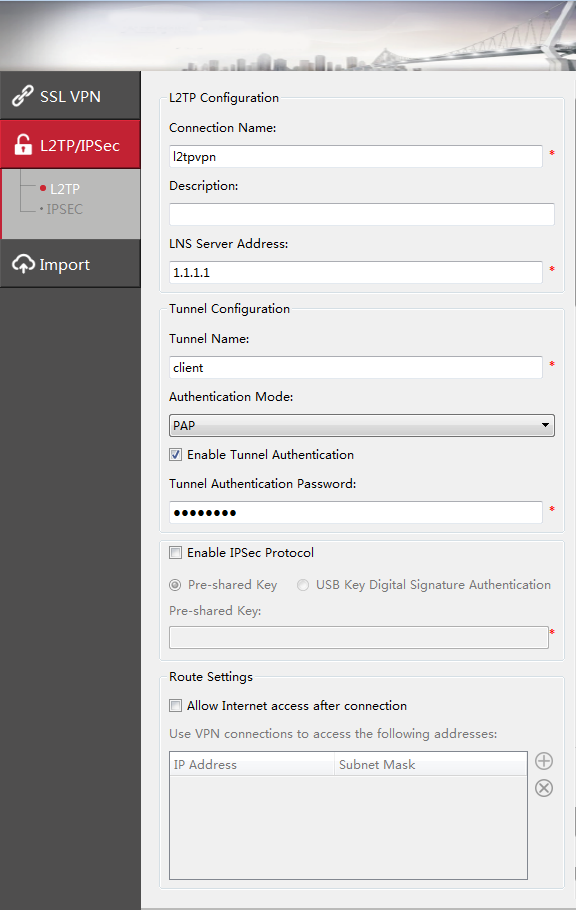
In the New Connection navigation tree, select L2TP/IPSec. Set connection parameters and click OK.
The tunnel authentication password is Hello123.
- Log in to the L2TP VPN gateway.
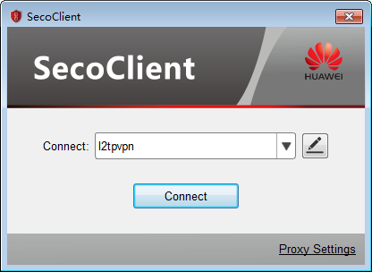
- Select the created L2TP VPN connection from the Connect drop-down list and click Connect.
- On the login page, enter the user name and password.
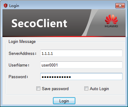
- Click Login to initiate a VPN connection request.
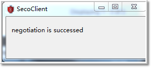
A message on a VPN access success will be displayed on the web UI. After the connection is established, mobile users can access intranet resources as intranet users.
- Select the created L2TP VPN connection from the Connect drop-down list and click Connect.
- Open the SecoClient and access the home page.
Verification
- Mobile users can properly access intranet servers of the headquarters.
Run the display l2tp tunnel command on the LNS. A tunnel is established. In the following command output, only the data generated when mobile employees of Enterprise1 access the LNS.
[LNS] display l2tp tunnel
 L2TP::Total Tunnel: 1

 LocalTID RemoteTID RemoteAddress    Port   Sessions RemoteName  VpnInstance
 ------------------------------------------------------------------------------
 1        1         2.2.2.2          1701    1                    vpn1
 ------------------------------------------------------------------------------
  Total 1, 1 printed
Configuration Scripts
Configuration script of the LNS
sysname LNS
#
 l2tp enable
#
ip vpn-instance vpn1
  route-distinguisher 100:1
ip vpn-instance vpn2
  route-distinguisher 200:1
#
ip pool enterprise1_pool
 section 1 10.1.1.2 10.1.1.100
ip pool enterprise2_pool
 section 1 10.1.2.2 10.1.2.100
#
aaa
 service-scheme scheme1
  ip-pool enterprise1_pool
 service-scheme scheme2
  ip-pool enterprise2_pool
 domain domain1
  service-type l2tp
 domain domain2
  service-type l2tp
#
l2tp-group 1
 allow l2tp virtual-template 1 remote client vpn-instance vpn1
 tunnel password cipher %$%$Gg)[J=_EM).Y2g@Lr8b@+S7=%$%$
l2tp-group 2
 allow l2tp virtual-template 2 remote client2 vpn-instance vpn2
 tunnel password cipher %$%$Gg)[J=_EM).Y2g@Lr8b@+S7=%$%$
#
interface Virtual-Template1
 ppp authentication-mode chap pap
 remote service-scheme scheme1
 ip binding vpn-instance vpn1
 ip address 10.1.1.1 255.255.255.0
interface Virtual-Template2
 ppp authentication-mode chap pap
 remote service-scheme scheme2
 ip binding vpn-instance vpn2
 ip address 10.1.2.1 255.255.255.0
#
interface GigabitEthernet0/0/1
 ip address 1.1.1.1 255.255.255.0
#
interface GigabitEthernet0/0/2
 ip binding vpn-instance vpn1
 ip address 192.168.1.1 255.255.255.0
#
interface GigabitEthernet0/0/3
 ip binding vpn-instance vpn2
 ip address 172.16.1.1 255.255.255.0
#
firewall zone trust
 add interface GigabitEthernet0/0/2
 add interface GigabitEthernet0/0/3
#
firewall zone untrust
  add interface GigabitEthernet0/0/1
#
firewall zone dmz
 add interface Virtual-Template1
 add interface Virtual-Template2
#
security-policy
 rule name rule name service_dt
  source-zone dmz
  destination-zone trust
  source-address 10.1.1.0 mask 255.255.255.0
  source-address 10.1.2.0 mask 255.255.255.0
  destination-address 192.168.2.0 mask 255.255.255.0
  destination-address 172.16.2.0 mask 255.255.255.0
  action permit
 rule name service_td
  source-zone trust
  destination-zone dmz
  source-address 192.168.2.0 mask 255.255.255.0
  source-address 172.16.2.0 mask 255.255.255.0
  destination-address 10.1.1.0 mask 255.255.255.0
  destination-address 10.1.2.0 mask 255.255.255.0
  action permit
 rule name l2tp_ul
  source-zone untrust
  destination-zone local
  destination-address 1.1.1.0 mask 255.255.255.0
  action permit
# The following configurations for creating users are stored in the database, not described in the configuration file.
user-manage group /default/enterprise1
user-manage group /default/enterprise2
user-manage user user0001
 parent-group /default/enterprise1
 password *********
user-manage user user0002
 parent-group /default/enterprise2
 password *********
#
return