Web UI: Example for Configuring L2TP VPN (RADIUS Authentication) in the Client-Initiated Scenario
This section provides an example for configuring L2TP VPN in the client-initiated scenario. In the client-initiated scenario, the LNS works with the RADIUS server to perform identity authentication for mobile users.
Networking Requirements
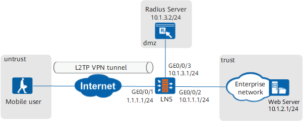
Data Planning
Item |
Data |
|
|---|---|---|
LNS |
Interface |
Interface ID: GigabitEthernet 0/0/1 IP address: 1.1.1.1/24 Security zone: Untrust Interface ID: GigabitEthernet 0/0/2 IP address: 10.1.1.1/24 Security zone: Trust Interface ID: GigabitEthernet 0/0/3 IP address: 10.1.3.1/24 Security zone: DMZ |
L2TP configuration |
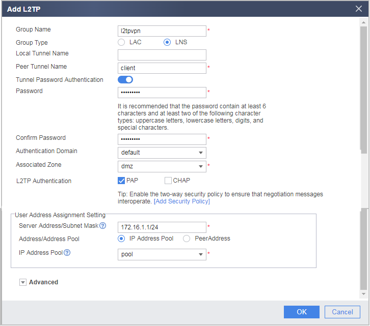
User name: user0001 Password: Password123 Peer tunnel name: client Tunnel authentication password: Hello123 Address pool: 172.16.1.2 to 172.16.1.100 NOTE:
If the intranet server IP address and address pool addresses are on different network segments, configure a route on the intranet server to an address in the address pool. |
|
Parameters for interconnection with the RADIUS server |
RADIUS server address: 10.1.3.2/24 Shard key: Radius123 |
|
Mobile user |
User name: user0001 Password: Password123 Tunnel name: client Tunnel authentication password: Hello123 |
|
Procedure
- Configure the LNS.
- Set IP addresses for interfaces and assign the interfaces to security zones.
- Set parameters for interconnecting with the RADIUS server.
- Choose . Click Add to set parameters for interconnecting with the RADIUS server.
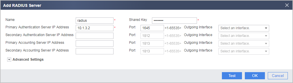
Click Test and then OK in the dialog box that is displayed. Then enter the account name and password obtained from the RADIUS server. Click Start to check the connectivity to the RADIUS server.
- Click OK.
- Choose . Click Add to set parameters for interconnecting with the RADIUS server.
- Configure the authentication domain.
Authentication domain default is used as an example. You can define an authentication domain.
- Choose Object > User > default and configure RADIUS server authentication.
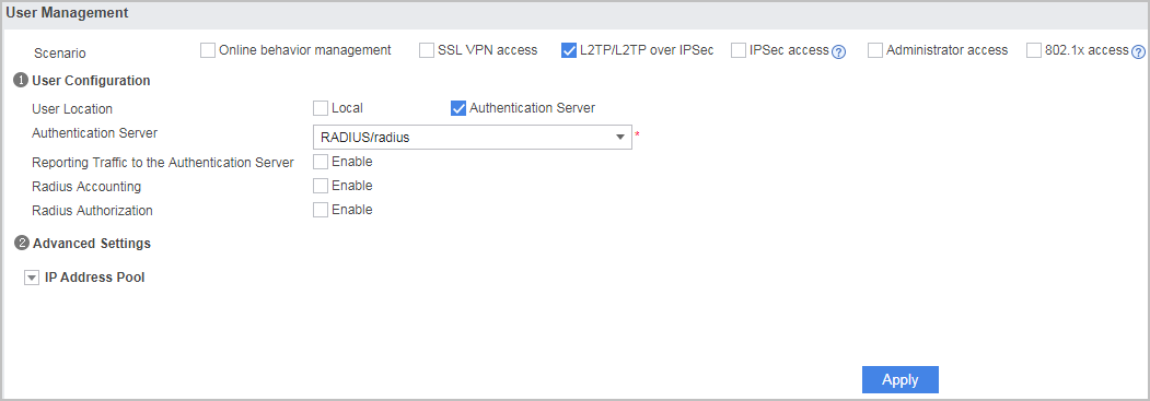
- Click Apply.
- Choose Object > User > default and configure RADIUS server authentication.
- Configure L2TP VPN.
- Choose .
In L2TP Group List, click Add and set L2TP parameters.
Set Password to Hello123 and the address range of Address/Address Pool to 172.16.1.2 to 172.16.1.100. Associated Zone indicates the security zone where the VT interface resides. Server Address/Subnet Mask is the address of the VT interface on the LNS side. It is recommended that the IP address be in the same network as the address pool.
- Click OK.
- Configure a RADIUS server. For how to configure a RADIUS server, see the documents of the RADIUS server.
- Configure the SecoClient at the mobile user side.
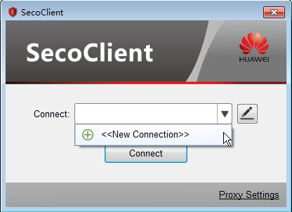
- Open the SecoClient and access the home page.
Select New Connection from the Connect drop-down list.
- Set L2TP VPN connection parameters.
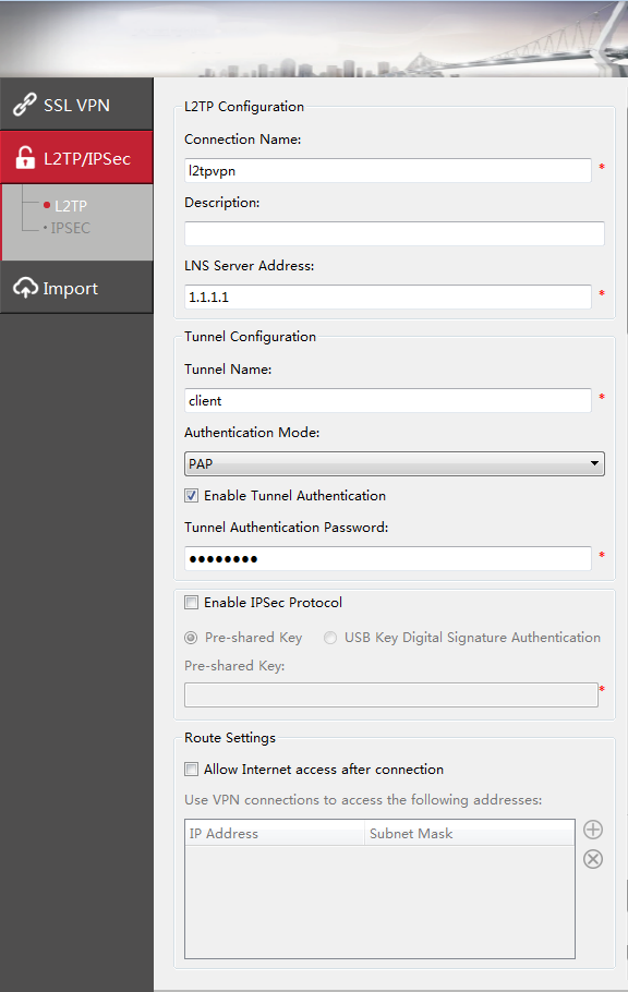
In the New Connection navigation tree, select L2TP/IPSec. Set connection parameters and click OK.
The tunnel authentication password is Hello123.
- Log in to the L2TP VPN gateway.
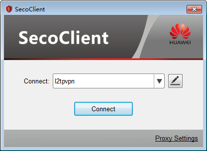
- Select the created L2TP VPN connection from the Connect drop-down list and click Connect.
- On the login page, enter the user name and password.
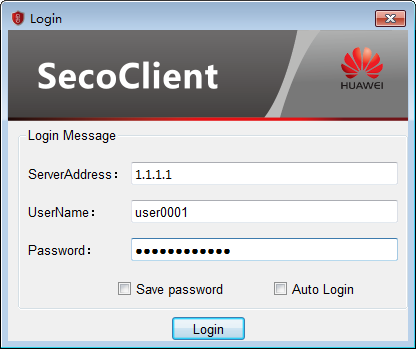
- Click Login to initiate a VPN connection request.
A message on a VPN access success will be displayed on the web UI. After the connection is established, mobile users can access intranet resources as intranet users.
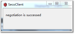
- Select the created L2TP VPN connection from the Connect drop-down list and click Connect.
- Open the SecoClient and access the home page.

Verification
- Log in to the LNS and choose to view the monitoring list. You can find that user user0001 has logged in to the device successfully.
- Mobile users can access intranet resources properly.
Configuration Scripts
#
sysname LNS
#
 l2tp enable
 undo l2tp sendaccm enable
 l2tp domain suffix-separator @
#
radius-server template radius
 radius-server shared-key cipher %^%#:1t2V{T>#;^e6c2&x1R-s-r<"r6^,+]@!s#jY;T%%^%#
 radius-server authentication 10.1.3.2 1645 weight 100
 radius-server group-filter class
#
ip pool pool
 section 0 172.16.1.2 172.16.1.100
#
ip route-static 0.0.0.0 0.0.0.0 1.1.1.2
#
aaa
 authentication-scheme admin_radius
  authentication-mode radius
 service-scheme l2tpSScheme_1497877787064
  ip-pool pool
 domain default
  radius-server radius
  authentication-scheme admin_radius
  service-type l2tp
#
l2tp-group l2tpvpn
 tunnel password cipher %$%$b:5QM(/k!4Qpp+Z0DV`${fn.%$%$
 allow l2tp virtual-template 1 remote client domain default
#
interface Virtual-Template1
 ppp authentication-mode pap
 remote service-scheme l2tpSScheme_1497877787064
 ip address 172.16.1.1 255.255.255.0
 alias L2TP_LNS_1
 undo service-manage enable
#
interface GigabitEthernet 0/0/1
 undo shutdown
 ip address 1.1.1.1 255.255.255.0
#
interface GigabitEthernet 0/0/2
 undo shutdown
 ip address 10.1.1.1 255.255.255.0
#
interface GigabitEthernet 0/0/3
 undo shutdown
 ip address 10.1.3.1 255.255.255.0
#
firewall zone trust
 set priority 85
 add interface GigabitEthernet 0/0/2
#
firewall zone untrust
 set priority 5
 add interface GigabitEthernet 0/0/1
#
firewall zone dmz
 set priority 85
 add interface GigabitEthernet 0/0/3
 add interface Virtual-Template1
#
security-policy
  rule name service_td
    source-zone trust
    destination-zone dmz
    source-address 10.1.2.0 24
    destination-address 172.16.1.0 mask 255.255.255.0
    action permit
  rule name service_dt
    source-zone dmz
    destination-zone trust
    source-address 172.16.1.0 mask 255.255.255.0
    destination-address 10.1.2.0 mask 255.255.255.0
    action permit
  rule name l2tp_ul
    source-zone untrust
    destination-zone local
    destination-address 1.1.1.0 mask 255.255.255.0
    action permit
  rule name radius_ld
   source-zone local
   destination-zone dmz
   source-address 10.1.3.0 mask 255.255.255.0
   action permit