Web: Example for Configuring NAPT for Users on a Dual-Egress Intranet to Access the Internet
This section provides an example for configuring NAPT for users on a dual-egress intranet to access the Internet.
Networking Requirements
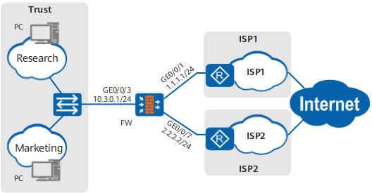
As shown in Figure 1, an enterprise deploys a FW as a security gateway on the intranet and purchases broadband services from ISP1 and ISP2.
The networking requirements are as follows:
- PCs of the R&D and marketing departments access the Internet through ISP1 and ISP2 networks. Intranet traffic is forwarded through ISP1 or ISP2 network to specified destination network segments.
- If the link to one ISP network fails, traffic is immediately switched to the link connected to the other ISP network.
The following information is used as an example. Obtain the desired service information from your local ISP.
Item |
Data |
Description |
|
|---|---|---|---|
Enterprise addresses |
1.1.1.1/24 |
Public network address that ISP1 assigns to the enterprise |
|
2.2.2.2/24 |
Public network address that ISP2 assigns to the enterprise |
||
Default gateway addresses |
1.1.1.254 |
Provided by ISP1 |
|
2.2.2.254 |
Provided by ISP2 |
||
DNS server addresses |
9.9.9.9 |
Provided by ISP1 |
|
11.11.11.11 |
Provided by ISP2 |
||
Addresses in an address pool |
1.1.1.10 - 1.1.1.12 |
Provided by ISP1 |
|
2.2.2.10 - 2.2.2.12 |
Provided by ISP2 |
||
Configuration Roadmap
The configuration roadmap is as follows:
- Assign IP addresses to interfaces and add the interfaces to security zones. Set the default gateway address to 1.1.1.254 for GigabitEthernet 0/0/1 and 2.2.2.254 for GigabitEthernet 0/0/7.
- Configure static routes to ISP networks.
- Configure security policies to allow PCs to access the Internet.
- Configure NAT policies for translating source addresses.
- Configure return routes on ISP devices. This step is performed by ISPs. The configuration details are not provided.
- Plan IP addresses for intranet PCs. Set the gateway address used by PCs to 10.3.0.1 and DNS server addresses to 9.9.9.9 and 11.11.11.11. This step is performed by a network administrator. Therefore, the configuration details are not provided.
Procedure
- Set IP addresses for interfaces on the FW and assign the interfaces to security zones.
- Set the IP address of GigabitEthernet 0/0/3 and assign the interface to a security zone.
- Set the IP address of GigabitEthernet 0/0/1 and assign the interface to a security zone.
- Set the IP address of GigabitEthernet 0/0/7 and assign the interface to a security zone.
- Configure a security policy to allow a specific intranet segment to access the Internet.
In Security Policy List, click Add, select Add Security Policy, and configure a security policy based on the following parameter values.
Name
policy1
Source Zone
trust
Destination Zone
isp1
Source Address/Region
10.3.0.0/24
Action
Permit
Repeat the preceding steps to configure security policy policy2.
Name
policy2
Source Zone
trust
Destination Zone
isp2
Source Address/Region
10.3.0.0/24
Action
Permit
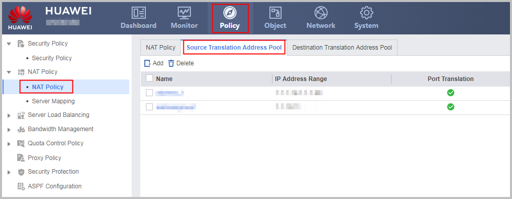
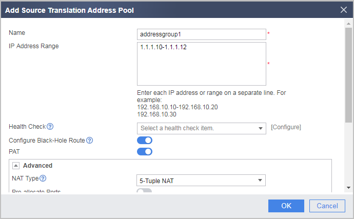
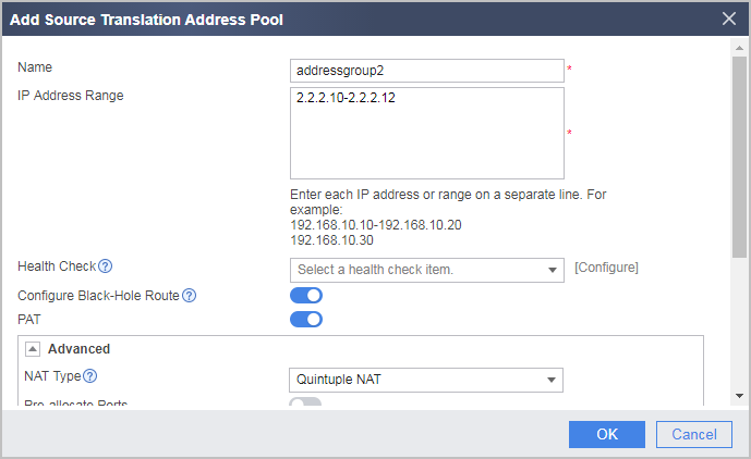
- Configure a NAT address pool.
- Configure a source NAT policy for translating source addresses between private and public address realms when hosts on the specific intranet segment access the Internet.
-
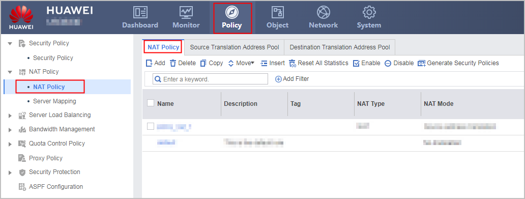
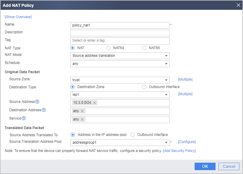
In NAT Policy List, click Add and configure a NAT policy based on the following parameter values, so that intranet users can access the Internet through ISP1 network.
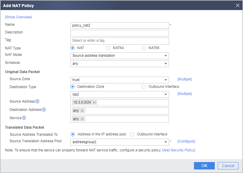
In NAT Policy List, click Add and configure a NAT policy based on the following parameter values, so that intranet users can access the Internet through ISP2 network.
-
- Configure static routes.

In the example, the packets destined for 1.1.2.0/24 and 1.1.3.0/24 are forwarded over ISP1 network, and the packets destined for 2.2.3.0/24 and 2.2.4.0/24 are forwarded over ISP2 network. Four static routes are configured in this example. In actual service configurations, you may need more static routes. Obtain the desired ISP network segment information from your local ISP.
To improve configuration efficiency, you can also use ISP link selection to quickly import ISP routes. For details, see Key Points for Configuring ISP Link Selection.
In Static Route List, click Add and configure a static route through which packets destined for 1.1.2.0/24 are forwarded through ISP1 network.
Protocol
IPv4
Destination Address/Mask
1.1.2.0/255.255.255.0
Next Hop
1.1.1.254
Repeat the preceding steps to configure other static routes. The configuration is omitted.

Configuration Scripts
Configuration script for the FW:
#
 sysname FW
#
interface GigabitEthernet0/0/1
 undo shutdown
 ip address 1.1.1.1 255.255.255.0
#
interface GigabitEthernet0/0/3
 undo shutdown
 ip address 10.3.0.1 255.255.255.0
#
interface GigabitEthernet0/0/7
 undo shutdown
 ip address 2.2.2.2 255.255.255.0
#
firewall zone trust
 set priority 85
 add interface GigabitEthernet0/0/3
#
firewall zone name isp1 id 4
 set priority 10
 add interface GigabitEthernet0/0/1
#
firewall zone name isp2 id 5
 set priority 20
 add interface GigabitEthernet0/0/7
#
 ip route-static 1.1.2.0 255.255.255.0 1.1.1.254
 ip route-static 1.1.3.0 255.255.255.0 1.1.1.254
 ip route-static 2.2.3.0 255.255.255.0 2.2.2.254
 ip route-static 2.2.4.0 255.255.255.0 2.2.2.254
 ip route-static 0.0.0.0 255.255.255.0 1.1.1.254
 ip route-static 0.0.0.0 255.255.255.0 2.2.2.254
#
nat address-group addressgroup1 0
 mode pat
 route enable
 section 0 1.1.1.10 1.1.1.12
#
nat address-group addressgroup2 1
 mode pat
 route enable
 section 0 2.2.2.10 2.2.2.12
#
security-policy
  rule name policy1
    source-zone trust
    destination-zone isp1
    source-address 10.3.0.0 24
    action permit
  rule name policy2
    source-zone trust
    destination-zone isp2
    source-address 10.3.0.0 24
    action permit
#
nat-policy
  rule name policy_nat1
    source-zone trust
    destination-zone isp1
    source-address 10.3.0.0 24
    action source-nat address-group addressgroup1
  rule name policy_nat2
    source-zone trust
    destination-zone isp2
    source-address 10.3.0.0 24
    action source-nat address-group addressgroup2
#
return