Web: Example for Configuring NAPT for Users on a Layer-2 Intranet to Access the Internet
This section provides an example for configuring NAPT for users on a Layer-2 intranet to access the Internet.
Networking Requirements
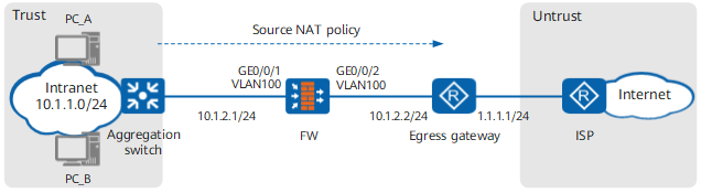
As shown in Figure 1, the FW is deployed in transparent mode to keep the network topology unchanged. Its upstream and downstream interfaces work in Layer-2 mode.
A source NAT policy must be configured on the FW to allow users in network segment 10.1.1.0/24 to access the Internet. In addition to public IP addresses of interfaces on the egress gateway, the enterprise applies for six IP addresses (1.1.1.10 to 1.1.1.15) for NAT.
Data Planning
Item |
Data |
Description |
|
|---|---|---|---|
GigabitEthernet 0/0/1 |
VLAN: 100 Security zone: trust |
- |
|
GigabitEthernet 0/0/2 |
VLAN: 100 Security zone: untrust |
- |
|
Intranet segment that is allowed to access the Internet |
10.1.1.0/24 |
- |
|
Public addresses mapped to private addresses |
1.1.1.10 to 1.1.1.15 |
As private addresses far outnumber public addresses, one-to-one mapping cannot be implemented. To translate all private addresses into public addresses, enable port translation. |
|
Routing information |
Black-hole routes on the aggregation switch |
Destination address: 1.1.1.10 to 1.1.1.15 Next hop: NULL0 |
Routing loops are made between the aggregation switch and egress gateway to prevent Internet users from accessing the after-NAT public addresses. |
Static routes on the egress gateway |
Destination address: 1.1.1.10 to 1.1.1.15 Next hop: 10.1.2.1 |
- |
|
Static routes on the ISP router |
Destination address: 1.1.1.10 to 1.1.1.15 Next hop address: 1.1.1.1 |
The public addresses mapped to private addresses are not assigned to physical ports. As a result, the router cannot use a routing protocol to discover routes to the public addresses. Ask the ISP network administrator to configure a static route destined for the network segment address of the address pool on the router. |
|
Configuration Roadmap
The configuration roadmap is as follows:
- Switch interfaces to the Layer 2 mode, add them to a VLAN and a security zone, and complete basic network parameter settings.
- Configure a security policy to allow a specific intranet segment to access the Internet.
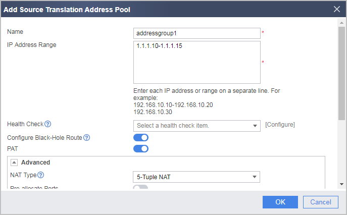
- Configure a NAT address pool and enable port translation.
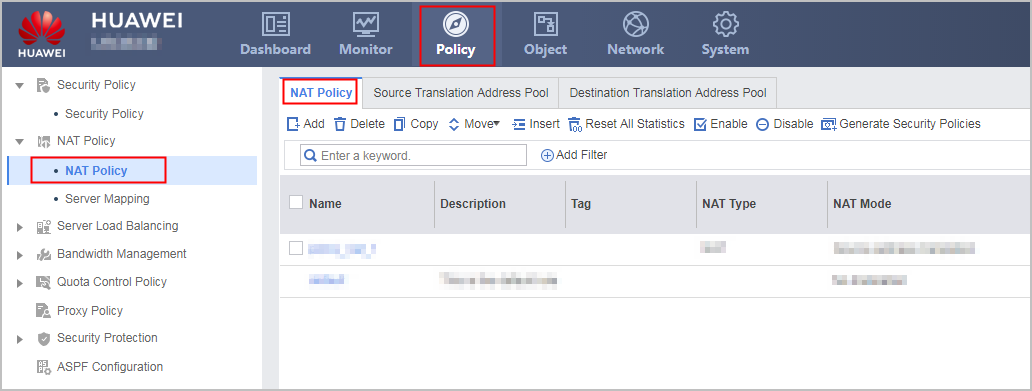
- Configure a source NAT policy for translating source addresses between private and public address realms when hosts on the specific intranet segment access the Internet.
Procedure
- Add the interfaces to security zones, and configure network connectivity
- Assign GigabitEthernet 0/0/1 to a security zone.
- Assign GigabitEthernet 0/0/2 to a security zone.
- Configure a security policy to allow a specific intranet segment to access the Internet.
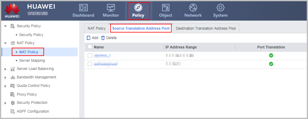
- Configure a NAT address pool and a NAT policy.
- Configure black-hole routes to the NAT address pool (1.1.1.10 to 1.1.1.15) on the aggregation switch. The following part uses a Huawei switch to illustrate the configuration:
<switch> system-view
[switch] ip route-static 1.1.1.10 32 NULL0
[switch] ip route-static 1.1.1.11 32 NULL0
[switch] ip route-static 1.1.1.12 32 NULL0
[switch] ip route-static 1.1.1.13 32 NULL0
[switch] ip route-static 1.1.1.14 32 NULL0
[switch] ip route-static 1.1.1.15 32 NULL0
- Configure static routes to the NAT address pool (1.1.1.10 to 1.1.1.15) on the egress gateway, with the next hop being 10.1.2.1. The following part uses a Huawei switch to illustrate the configuration:
<router> system-view
[router] ip route-static 1.1.1.10 32 10.1.2.1
[router] ip route-static 1.1.1.11 32 10.1.2.1
[router] ip route-static 1.1.1.12 32 10.1.2.1
[router] ip route-static 1.1.1.13 32 10.1.2.1
[router] ip route-static 1.1.1.14 32 10.1.2.1
[router] ip route-static 1.1.1.15 32 10.1.2.1
- Configure static routes to the NAT address pool (1.1.1.10 to 1.1.1.15) on the ISP router, with the next hop being 1.1.1.1, so that traffic returned from the Internet can be forwarded to the enterprise egress gateway.
Contact your ISP administrator to perform this step.

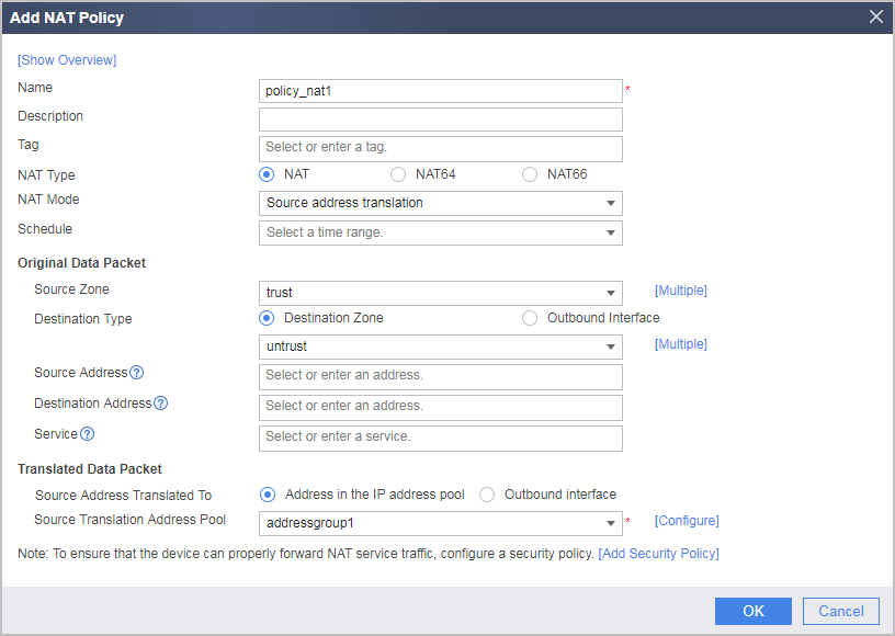
Configuration Scripts
Configuration script for the FW:
#
 sysname FW
#
vlan batch 100
#
interface GigabitEthernet0/0/1
 portswitch
 undo shutdown
 port link-type access
 port default vlan 100
#
interface GigabitEthernet0/0/2
 portswitch
 undo shutdown
 port link-type access
 port default vlan 100
#
firewall zone trust
 set priority 85
 add interface GigabitEthernet0/0/1
#
firewall zone untrust
 set priority 5
 add interface GigabitEthernet0/0/2
#
nat address-group addressgroup1 0
 mode pat
 route enable
 section 0 1.1.1.10 1.1.1.15
#
security-policy
  rule name policy1
    source-zone trust
    destination-zone untrust
    source-address 10.1.1.0 24
    action permit
#
nat-policy
  rule name policy_nat1
    source-zone trust
    destination-zone untrust
    source-address 10.1.1.0 24
    action source-nat address-group addressgroup1
#
return