Web: Example for Configuring Load Balancing by Link Quality
After load balancing by link quality is configured, the FW can forward traffic through the link of the best quality.
Networking Requirements
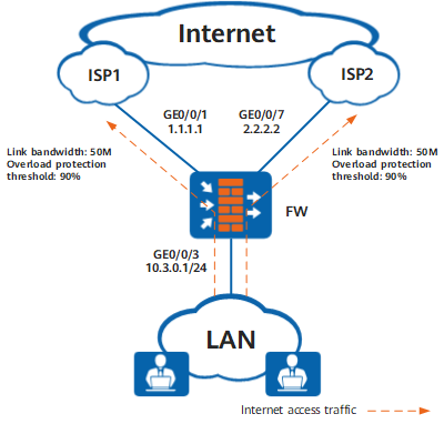
As shown in Figure 1, an enterprise has two 50M links connected respectively to ISP1 and ISP2.
Configuration Roadmap
Set the intelligent uplink selection mode to load balancing by link quality. To ensure that the FW can use other links to forward traffic when a link is faulty or overloaded, you need to configure health check and link overload protection functions.
- Configure the health check function. Configure a health check respectively for ISP1 and ISP2.
Set the interface IP address, security zone, gateway, bandwidth, and overload protection threshold, and apply the health check respectively on the interfaces.
Configure global route selection policies. Set the intelligent uplink selection mode to load balancing by link quality and configure the outbound interfaces on the FW connecting to ISP1 and ISP2 networks as intelligent uplink selection member interfaces.
Configure a basic security policy to allow intranet users to access the Internet.

This example focuses on the configuration related to intelligent uplink selection. Configure other data such as NAT based on the actual networking.
Procedure
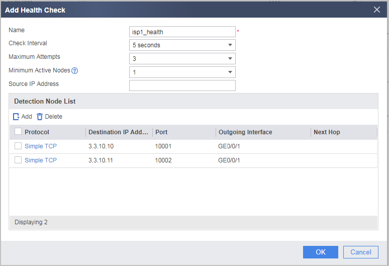
- Enable the health check function and create health check tasks for ISP1 and ISP2 links. Assume that the destination network segment of ISP1 is 3.3.10.0/24, and the destination network segment of ISP2 is 9.9.20.0/24.
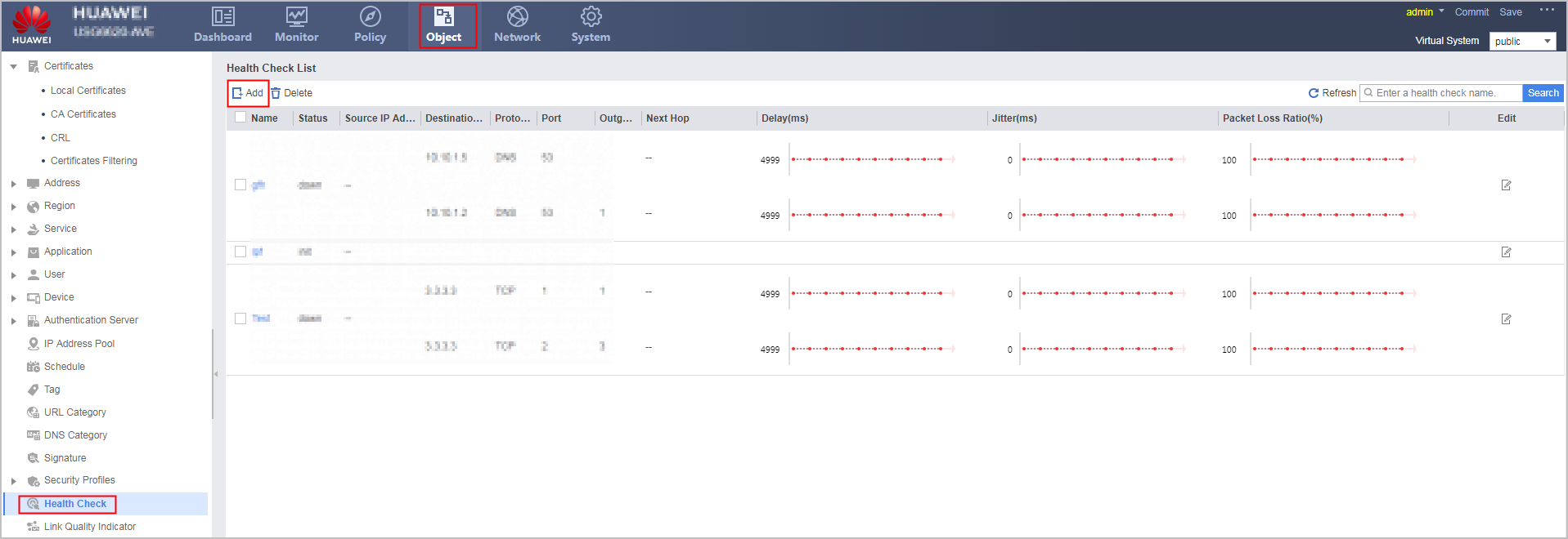
Choose . Click Add in the Health Check List area to create a health check task for ISP1 link.
Click Add to create a health check task for ISP2 link.
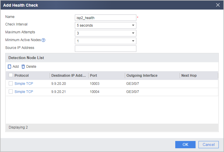
Assume that 3.3.10.10 and 3.3.10.11 are known device addresses on the ISP1 network and that 9.9.20.20 and 9.9.20.21 are known device addresses on the ISP2 network.
If the state remains down after the health check configuration is complete, check the health check configuration.
- Set IP and gateway addresses for GigabitEthernet 0/0/1 and GigabitEthernet 0/0/7, assign the interfaces to the Untrust zone, set the bandwidth values and overload protection thresholds for the links of the interfaces, and apply health check.
Choose and click
 on the line of the interface to be configured.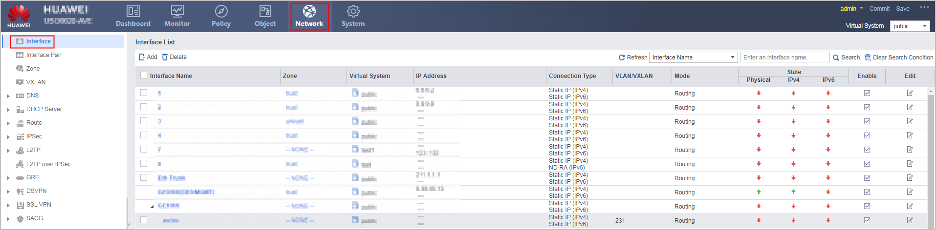
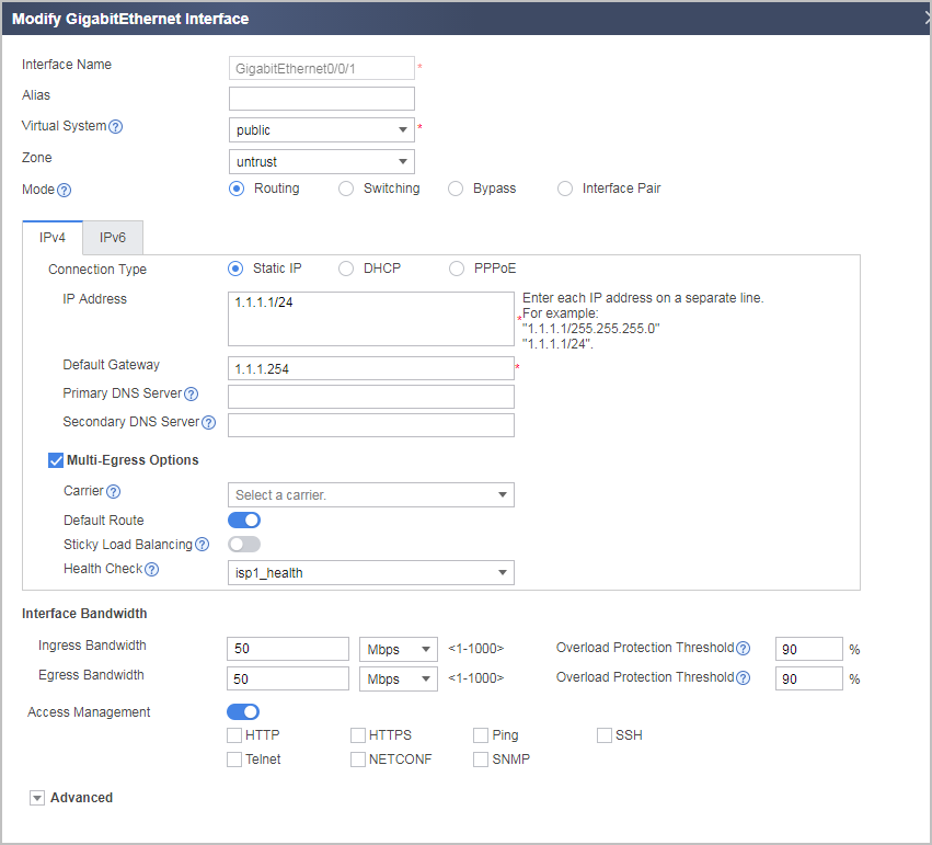
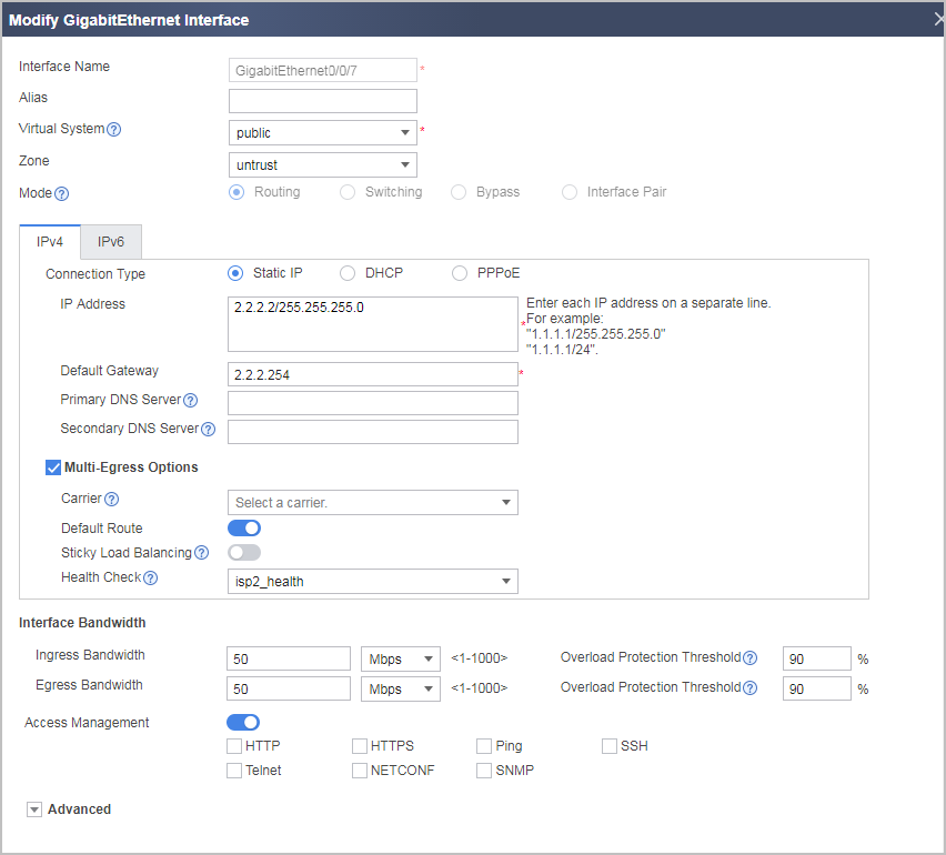
- Configure an IP address for GigabitEthernet 0/0/3 and assign the interface to the Trust zone.
Choose and click
on the line of the interface to be configured.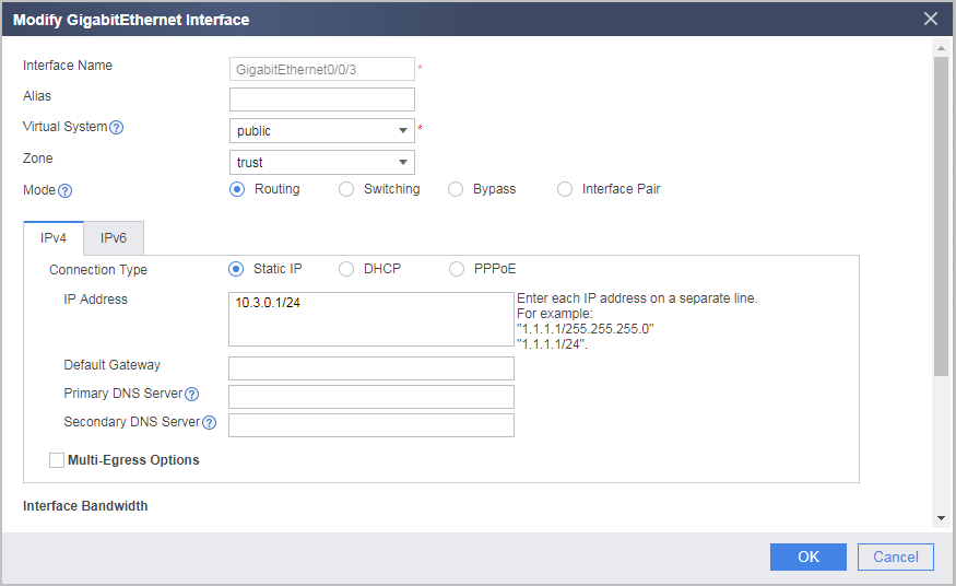
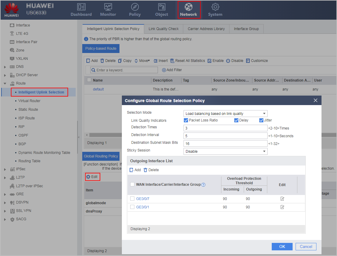
- Configure a global route selection policy, set load balancing by link quality, and add GigabitEthernet 0/0/1 and GigabitEthernet 0/0/7 to the outgoing interface list.
Choose . In the Global Routing Policy area, click Edit.
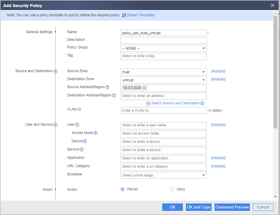
- Configure a Trust-to-Untrust interzone security policy to allow enterprise network users to access Internet resources. Assume that enterprise network users reside on 10.3.0.0/24.
Choose and click Add Security Policy to create a security policy.
Configuration Scripts
#
healthcheck enable
healthcheck name isp1_health
 destination 3.3.10.10 interface GigabitEthernet0/0/1 protocol tcp-simple destination-port 10001
 destination 3.3.10.11 interface GigabitEthernet0/0/1 protocol tcp-simple destination-port 10002
healthcheck name isp2_health
 destination 9.9.20.20 interface GigabitEthernet0/0/7 protocol tcp-simple destination-port 10003
 destination 9.9.20.21 interface GigabitEthernet0/0/7 protocol tcp-simple destination-port 10004
#
interface GigabitEthernet0/0/1
 ip address 1.1.1.1 255.255.255.0
 gateway 1.1.1.254
 bandwidth ingress 50000 threshold 90
 bandwidth egress 50000 threshold 90
 healthcheck isp1_health
#
interface GigabitEthernet0/0/3
 ip address 10.3.0.1 255.255.255.0
#
interface GigabitEthernet0/0/7
 ip address 2.2.2.2 255.255.255.0
 gateway 2.2.2.254
 bandwidth ingress 50000 threshold 90
 bandwidth egress 50000 threshold 90
 healthcheck isp2_health
#
 firewall zone trust
  set priority 85
  add interface GigabitEthernet0/0/3
#
firewall zone untrust
 set priority 5
 add interface GigabitEthernet0/0/1
 add interface GigabitEthernet0/0/7
#
 multi-interface
  mode priority-of-link-quality
  priority-of-link-quality parameter delay jitter loss
  priority-of-link-quality protocol tcp-simple
  add interface GigabitEthernet0/0/1
  add interface GigabitEthernet0/0/7
#
security-policy
 rule name policy_sec_trust_untrust
  source-zone trust
  destination-zone untrust
  source-address 10.3.0.0 mask 255.255.255.0
  action permit
#
return