Web UI: Example for Configuring Across-Layer-3 MAC Identification
This section provides an example for configuring across-Layer-3 MAC identification on the web UI.
Networking Requirements
The FW functions as the egress gateway on the enterprise network. Intranet users connect to the FW through a Layer-3 switch and access the Internet through the FW. You need to configure security policies, policy-based routes, and traffic policies on the FW for it to control intranet traffic matching the specified MAC address.

Configuration Roadmap
If the FW is connected to an intranet PC with a Layer-3 switch in between, the FW cannot directly obtain the MAC address of the intranet PC. In such cases, you need to configure across-Layer-3 MAC identification on the FW for it to use SNMP to learn the ARP table of the switch and thus obtain the MAC address of the intranet PC.
Configure basic SNMP functions on the switch.
- Enable the SNMP agent function.
- Set the SNMP version.
- Set a community name for the switch.
Configure across-Layer-3 MAC identification on the FW.
- Configure a security policy for the Local -> Trust interzone to allow the firewall to send SNMP packets to the switch.
- Configure across-Layer-3 MAC identification.

- The Layer-3 switch needs to support public MIB object 1.3.6.1.2.1.4.22.1.2.
- Cross-Layer-3 MAC identification cannot be associated with IP-MAC binding.
Procedure
- This example uses Huawei S5700 as an example to describe how to configure basic SNMP functions. For basic network parameter settings of the switch, refer to the S5700 product documentation.
- Set a community name for the switch.
[Switch] snmp-agent community read Public@123
The community name set on the switch must be the same as that specified on the FW.
- Set a community name for the switch.
- Configure across-Layer-3 MAC identification on the FW.
- Configure across-Layer-3 MAC identification.
Choose , enable across-Layer-3 MAC identification, and set parameters as follows:
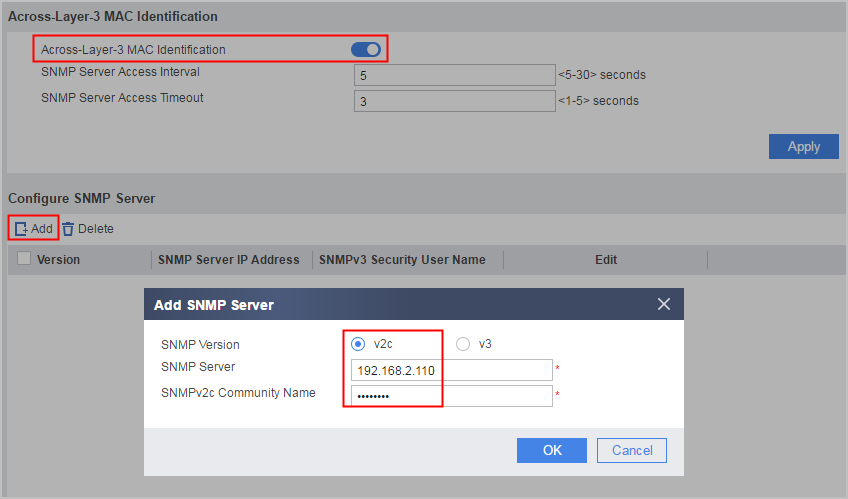
- If multiple Layer-3 devices are deployed between the FW and intranet PC, you need to specify the intranet PC as the target network device.
- You can also specify multiple Layer-3 devices on different subnets as SNMP clients for the FW to obtain their ARP entries.
- Configure across-Layer-3 MAC identification.
- Check learned MAC addresses.
<sysname> display snmp-server arp-sync table
2018-01-04 18:58:08.370
Synchronization status of the IP-MAC address mapping table:  Done
The start time of synchronizing IP-MAC mapping table: 2018/1/4 18:58:04
The end time of synchronizing IP-MAC mapping table: 2018/1/4 18:58:04
-----------------------------------------------------------------
IP Address          MAC Address     Expire(M)  VPN Instance
-----------------------------------------------------------------
10.1.141.1          e468-****-6cbc  20
10.1.141.132        00e0-****-0010  20
10.1.141.152        000c-****-f4ca  20
10.1.141.153        000c-****-e75f  20
10.1.141.165        0050-****-2329  20
10.1.141.201        80fb-****-928e  20
10.1.141.202        80fb-****-928e  20
192.168.2.100       000c-****-d3f4  20
192.168.2.110       000c-****-f4de  20
192.168.4.100     0050-****-ed9f  20
192.168.4.110     0050-****-49d3  20
-----------------------------------------------------------------
Total:11
- After the preceding configurations are complete, you can use the MAC address of the intranet PC as the policy matching condition when configuring service-specific security policies, policy-based routes, traffic policies, and audit policies.
A security policy is used as an example to set an intranet MAC address as a source address.
- In Source Address/Region, create a security policy, enter the learned intranet MAC address, and click OK.Figure 2 Adding an intranet MAC address
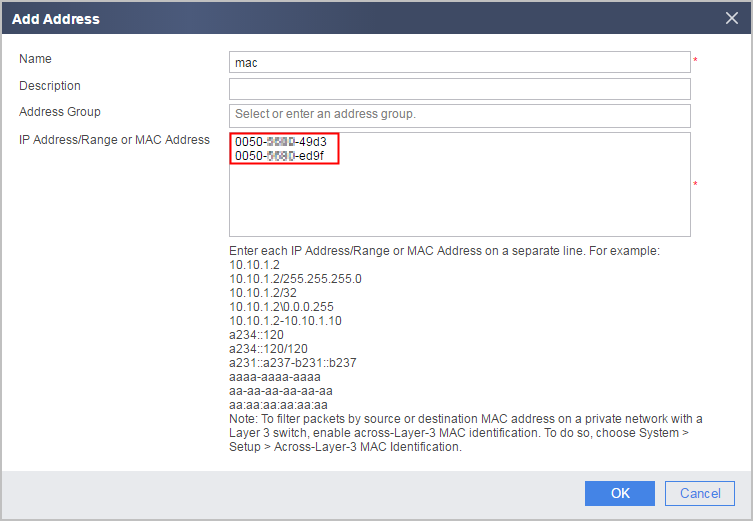
- In Source Address/Region, create a security policy, enter the learned intranet MAC address, and click OK.
Configuration Scripts
#
 sysname FW
#
interface GigabitEthernet0/0/2
 ip address 192.168.2.100 255.255.255.0
#
firewall zone trust
 set priority 85
 add interface GigabitEthernet0/0/2
#
 snmp-server arp-sync enable
 snmp-server arp-sync interval 5 timeout 3
 snmp-server target-host arp-sync address 192.168.2.110 community %$%$9]8wKc7.fV7EYJ=LCG[WP,#w%$%$ v2c
#
security-policy
 rule name policy_sec
  source-zone local
  destination-zone trust
  destination-address 192.168.2.110 255.255.255.255
  action permit
#
return