CLI: Load Balancing Networking in Which the Firewalls Work as the Gateways and Multi-ISP Accesses Are Provided
This section provides an example of configuring hot standby in load balancing mode in which multi-ISP accesses are provided, the service interfaces work at Layer 3 and are upstream and downstream connected to switches.
Networking Requirements
As shown in Figure 1, service interfaces of the two FW devices work at Layer 3, having upstream and downstream connections to Layer-2 switches. The upstream two switches are connected to two ISPs. ISP1 assigns the IP addresses of 1.1.1.1, 1.1.1.2, and 1.1.1.3, and ISP2 assigns the IP addresses of 2.2.2.1, 2.2.2.2, and 2.2.2.3 to the enterprise. Now, the two FW devices are supposed to work in load balancing mode so that traffic from Dept. A (IP address range: 10.3.0.51 to 10.3.0.100) goes to ISP1 and traffic from Dept. B (IP address range: 10.3.0.101 to 10.3.0.150) goes to ISP2. Normally, both FW_A and FW_B forward traffic. If either FW fails, the other FW forwards all traffic to ensure service continuity.
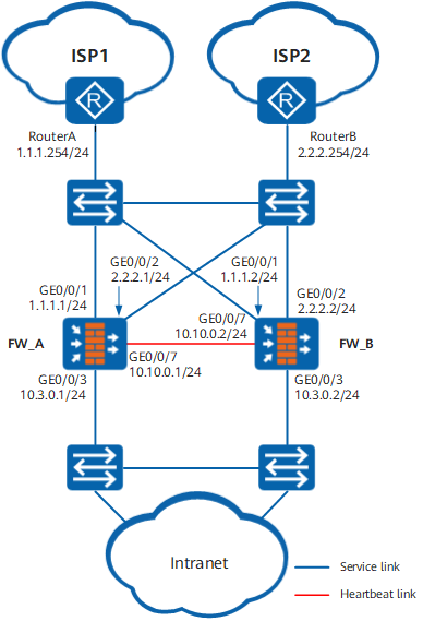
Procedure
- Set an IP address for each interface, assign interfaces to security zones, and complete basic parameter settings.
FW_A
FW_B
# Set IP addresses for the interfaces on FWs.
<FW_A> system-view
[FW_A] interface GigabitEthernet 0/0/1
[FW_A-GigabitEthernet0/0/1] ip address 1.1.1.1 24
[FW_A-GigabitEthernet0/0/1] quit
[FW_A] interface GigabitEthernet 0/0/2
[FW_A-GigabitEthernet0/0/2] ip address 2.2.2.1 24
[FW_A-GigabitEthernet0/0/2] quit
[FW_A] interface GigabitEthernet 0/0/3
[FW_A-GigabitEthernet0/0/3] ip address 10.3.0.1 24
[FW_A-GigabitEthernet0/0/3] quit
[FW_A] interface GigabitEthernet 0/0/7
[FW_A-GigabitEthernet0/0/7] ip address 10.10.0.1 24
[FW_A-GigabitEthernet0/0/7] quit
<FW_B> system-view
[FW_B] interface GigabitEthernet 0/0/1
[FW_B-GigabitEthernet0/0/1] ip address 1.1.1.2 24
[FW_B-GigabitEthernet0/0/1] quit
[FW_B] interface GigabitEthernet 0/0/2
[FW_B-GigabitEthernet0/0/2] ip address 2.2.2.2 24
[FW_B-GigabitEthernet0/0/2] quit
[FW_B] interface GigabitEthernet 0/0/3
[FW_B-GigabitEthernet0/0/3] ip address 10.3.0.2 24
[FW_B-GigabitEthernet0/0/3] quit
[FW_B] interface GigabitEthernet 0/0/7
[FW_B-GigabitEthernet0/0/7] ip address 10.10.0.2 24
[FW_B-GigabitEthernet0/0/7] quit
# Assign the interfaces to security zones on FWs.
[FW_A] firewall zone name isp1
[FW_A-zone-isp1] set priority 10
[FW_A-zone-isp1] add interface GigabitEthernet 0/0/1
[FW_A-zone-isp1] quit
[FW_A] firewall zone name isp2
[FW_A-zone-isp2] set priority 15
[FW_A-zone-isp2] add interface GigabitEthernet 0/0/2
[FW_A-zone-isp2] quit
[FW_A] firewall zone trust
[FW_A-zone-trust] add interface GigabitEthernet 0/0/3
[FW_A-zone-trust] quit
[FW_A] firewall zone dmz
[FW_A-zone-dmz] add interface GigabitEthernet 0/0/7
[FW_A-zone-dmz] quit
[FW_B] firewall zone name isp1
[FW_B-zone-isp1] set priority 10
[FW_B-zone-isp1] add interface GigabitEthernet 0/0/1
[FW_B-zone-isp1] quit
[FW_B] firewall zone name isp2
[FW_B-zone-isp2] set priority 15
[FW_B-zone-isp2] add interface GigabitEthernet 0/0/2
[FW_B-zone-isp2] quit
[FW_B] firewall zone trust
[FW_B-zone-trust] add interface GigabitEthernet 0/0/3
[FW_B-zone-trust] quit
[FW_B] firewall zone dmz
[FW_B-zone-dmz] add interface GigabitEthernet 0/0/7
[FW_B-zone-dmz] quit
- Configure PBR.
FW_A
FW_B
[FW_A] policy-based-route
[FW_A-policy-pbr] rule name route_policy_isp1
[FW_A-policy-pbr-rule-route_policy_isp1] source-zone trust
[FW_A-policy-pbr-rule-route_policy_isp1] source-address range 10.3.0.51 10.3.0.100
[FW_A-policy-pbr-rule-route_policy_isp1] action pbr next-hop 1.1.1.254
[FW_A-policy-pbr-rule-route_policy_isp1] quit
[FW_A-policy-pbr] rule name route_policy_isp2
[FW_A-policy-pbr-rule-route_policy_isp2] source-zone trust
[FW_A-policy-pbr-rule-route_policy_isp2] source-address range 10.3.0.101 10.3.0.150
[FW_A-policy-pbr-rule-route_policy_isp2] action pbr next-hop 2.2.2.254
[FW_A-policy-pbr-rule-route_policy_isp2] quit
[FW_A-policy-pbr] quit
[FW_B] policy-based-route
[FW_B-policy-pbr] rule name route_policy_isp1
[FW_B-policy-pbr-rule-route_policy_isp1] source-zone trust
[FW_B-policy-pbr-rule-route_policy_isp1] source-address range 10.3.0.51 10.3.0.100
[FW_B-policy-pbr-rule-route_policy_isp1] action pbr next-hop 1.1.1.254
[FW_B-policy-pbr-rule-route_policy_isp1] quit
[FW_B-policy-pbr] rule name route_policy_isp2
[FW_B-policy-pbr-rule-route_policy_isp2] source-zone trust
[FW_B-policy-pbr-rule-route_policy_isp2] source-address range 10.3.0.101 10.3.0.150
[FW_B-policy-pbr-rule-route_policy_isp2] action pbr next-hop 2.2.2.254
[FW_B-policy-pbr-rule-route_policy_isp2] quit
[FW_B-policy-pbr] quit
- Configure hot standby.
FW_A
FW_B
# Configure VRRP group 1 on GE0/0/1 on FW_A and set the status of VRRP group 1 to Active. Configure VRRP group 1 on GE0/0/1 on FW_B and set the status of VRRP group 1 to Standby.
[FW_A] interface GigabitEthernet 0/0/1
[FW_A-GigabitEthernet0/0/1] vrrp vrid 1 virtual-ip 1.1.1.3 active
[FW_A-GigabitEthernet0/0/1] quit
[FW_B] interface GigabitEthernet 0/0/1
[FW_B-GigabitEthernet0/0/1] vrrp vrid 1 virtual-ip 1.1.1.3 standby
[FW_B-GigabitEthernet0/0/1] quit
# Configure VRRP group 2 on GE0/0/2 on FW_A and set the status of VRRP group 2 to Standby. Configure VRRP group 2 on GE0/0/2 on FW_B and set the status of VRRP group 2 to Active.
[FW_A] interface GigabitEthernet 0/0/2
[FW_A-GigabitEthernet0/0/2] vrrp vrid 2 virtual-ip 2.2.2.3 standby
[FW_A-GigabitEthernet0/0/2] quit
[FW_B] interface GigabitEthernet 0/0/2
[FW_B-GigabitEthernet0/0/2] vrrp vrid 2 virtual-ip 2.2.2.3 active
[FW_B-GigabitEthernet0/0/2] quit
# Configure VRRP groups 3 and 4 on GE0/0/3 on FW_A and set the status of VRRP group 3 to Active and status of VRRP group 4 to Standby. Configure VRRP group 3 and 4 on GE0/0/3 on FW_B and set the status of VRRP group 3 to Standby and status of VRRP group 4 to Active.
[FW_A] interface GigabitEthernet 0/0/3
[FW_A-GigabitEthernet0/0/3] vrrp vrid 3 virtual-ip 10.3.0.3 active
[FW_A-GigabitEthernet0/0/3] vrrp vrid 4 virtual-ip 10.3.0.4 standby
[FW_A-GigabitEthernet0/0/3] quit
[FW_B] interface GigabitEthernet 0/0/3
[FW_B-GigabitEthernet0/0/3] vrrp vrid 3 virtual-ip 10.3.0.3 standby
[FW_B-GigabitEthernet0/0/3] vrrp vrid 4 virtual-ip 10.3.0.4 active
[FW_B-GigabitEthernet0/0/3] quit
# Configure quick session backup on both FWs in case of inconsistent forward and return packet paths.
[FW_A] hrp mirror session enable[FW_B] hrp mirror session enable# Specify the heartbeat interface and enable hot standby on FWs.
[FW_A] hrp interface GigabitEthernet 0/0/7 remote 10.10.0.2
[FW_A] hrp enable
[FW_B] hrp interface GigabitEthernet 0/0/7 remote 10.10.0.1
[FW_B] hrp enable
- Configure a security policy.
After hot standby relationship is established, security policies configured on FW_A are automatically backed up to FW_B.
[FW_A] security-policy
[FW_A-policy-security] rule name policy_sec
[FW_A-policy-security-rule-policy_sec] source-zone trust
[FW_A-policy-security-rule-policy_sec] destination-zone isp1 isp2
[FW_A-policy-security-rule-policy_sec] action permit
[FW_A-policy-security-rule-policy_sec] quit
[FW_A-policy-security] quit
- Configure a NAT policy to allow intranet users to access the Internet by using the public IP address after NAT.
After hot standby relationship is established, NAT policies configured on FW_A are automatically backed up to FW_B.
# Configure an IP address pool.
HRP_M[FW_A] nat address-group 1
HRP_M[FW_A-address-group-1] section 0 1.1.1.3 1.1.1.3
HRP_M[FW_A-address-group-1] quit
HRP_M[FW_A] nat address-group 2
HRP_M[FW_A-address-group-2] section 0 2.2.2.3 2.2.2.3
HRP_M[FW_A-address-group-2] quit
# Configure a NAT policy.
HRP_M[FW_A] nat-policy
HRP_M[FW_A-policy-nat] rule name policy_nat_1
HRP_M[FW_A-policy-nat-rule-policy_nat_1] source-zone trust
HRP_M[FW_A-policy-nat-rule-policy_nat_1] destination-zone isp1
HRP_M[FW_A-policy-nat-rule-policy_nat_1] action source-nat address-group 1
HRP_M[FW_A-policy-nat-rule-policy_nat_1] quit
HRP_M[FW_A-policy-nat] rule name policy_nat_2
HRP_M[FW_A-policy-nat-rule-policy_nat_2] source-zone trust
HRP_M[FW_A-policy-nat-rule-policy_nat_2] destination-zone isp2
HRP_M[FW_A-policy-nat-rule-policy_nat_2] action source-nat address-group 2
HRP_M[FW_A-policy-nat-rule-policy_nat_2] quit
HRP_M[FW_A-policy-nat] quit
- Configure default routes on intranet devices. Set the next-hop address of the default route to the virtual IP address (10.3.0.3) of VRRP group 3 for a PC of department A and the virtual IP address (10.3.0.4) of VRRP group 4 for a PC of department B.
Configuration Script
FW_A |
FW_B |
|---|---|
# hrp enable hrp interface GigabitEthernet 0/0/7 remote 10.10.0.2 hrp mirror session enable # interface GigabitEthernet 0/0/1 ip address 1.1.1.1 255.255.255.0 vrrp vrid 1 virtual-ip 1.1.1.3 active # interface GigabitEthernet 0/0/2 ip address 2.2.2.1 255.255.255.0 vrrp vrid 2 virtual-ip 2.2.2.3 standby # interface GigabitEthernet 0/0/3 ip address 10.3.0.1 255.255.255.0 vrrp vrid 3 virtual-ip 10.3.0.3 active vrrp vrid 4 virtual-ip 10.3.0.4 standby # interface GigabitEthernet 0/0/7 ip address 10.10.0.1 255.255.255.0 # firewall zone trust set priority 85 add interface GigabitEthernet 0/0/3 # firewall zone dmz set priority 50 add interface GigabitEthernet0/0/7 # firewall zone isp1 set priority 10 add interface GigabitEthernet 0/0/1 # firewall zone isp2 set priority 15 add interface GigabitEthernet 0/0/2 # nat address-group 1 section 0 1.1.1.3 1.1.1.3 nat address-group 2 section 0 2.2.2.3 2.2.2.3 # security-policy rule name policy_sec source-zone trust destination-zone isp1 destination-zone isp2 action permit # policy-based-route rule name route_policy_isp1 source-zone trust source-address range 10.3.0.51 10.3.0.100 action pbr next-hop 1.1.1.254 rule name route_policy_isp2 source-zone trust source-address range 10.3.0.101 10.3.0.150 action pbr next-hop 2.2.2.254 # nat-policy rule name policy_nat_1 source-zone trust destination-zone isp1 action source-nat address-group 1 rule name policy_nat_2 source-zone trust destination-zone isp2 action source-nat address-group 2 |
# hrp enable hrp interface GigabitEthernet 0/0/7 remote 10.10.0.1 hrp mirror session enable # interface GigabitEthernet 0/0/1 ip address 1.1.1.2 255.255.255.0 vrrp vrid 1 virtual-ip 1.1.1.3 standby # interface GigabitEthernet 0/0/2 ip address 2.2.2.2 255.255.255.0 vrrp vrid 2 virtual-ip 2.2.2.3 active # interface GigabitEthernet 0/0/3 ip address 10.3.0.2 255.255.255.0 vrrp vrid 3 virtual-ip 10.3.0.3 standby vrrp vrid 4 virtual-ip 10.3.0.4 active # interface GigabitEthernet 0/0/7 ip address 10.10.0.2 255.255.255.0 # firewall zone trust set priority 85 add interface GigabitEthernet 0/0/3 # firewall zone dmz set priority 50 add interface GigabitEthernet0/0/7 # firewall zone isp1 set priority 10 add interface GigabitEthernet 0/0/1 # firewall zone isp2 set priority 15 add interface GigabitEthernet 0/0/2 # nat address-group 1 section 0 1.1.1.3 1.1.1.3 nat address-group 2 section 0 2.2.2.3 2.2.2.3 # security-policy rule name policy_sec source-zone trust destination-zone isp1 destination-zone isp2 action permit # policy-based-route rule name route_policy_isp1 source-zone trust source-address range 10.3.0.51 10.3.0.100 action pbr next-hop 1.1.1.254 rule name route_policy_isp2 source-zone trust source-address range 10.3.0.101 10.3.0.150 action pbr next-hop 2.2.2.254 # nat-policy rule name policy_nat_1 source-zone trust destination-zone isp1 action source-nat address-group 1 rule name policy_nat_2 source-zone trust destination-zone isp2 action source-nat address-group 2 |