IPSec Hot Standby
Firewalls support two hot standby modes: active/standby and load sharing. Select a proper mode based on the site requirements.

In a hot standby scenario, two gateways must have the same software and hardware configurations, including the number and positions of boards, hardware and driver versions, and system software version.
IPSec Hot Standby in Active/Standby Mode
As shown in Figure 1, FW_A1 (active) and FW_A2 (standby) are configured in VRRP group 1, and an IPSec tunnel is set up between VRRP group 1 and a physical interface on the branch gateway FW_B. When the physical interface of FW_A1, the link on the physical interface, or FW_A1 itself fails, traffic is switched to FW_A2 for IPSec encapsulation and forwarding. The IPSec tunnel is not torn down.
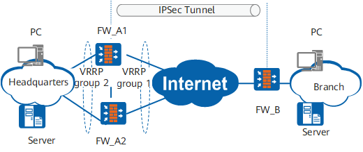
In active/standby mode, the standby device does not perform IPSec negotiation.
IPSec Hot Standby in Load Sharing Mode
The load sharing mode of IPSec hot standby is applicable to three LTE scenarios, in which load sharing is implemented differently.
IPSec gateways are configured to work in load sharing mode, and no backup IPSec tunnel is used.
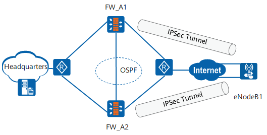
As shown in Figure 2, FW_A1 and FW_A2 work in load sharing mode. eNodeB1 sets up an IPSec tunnel with each of FW_A1 and FW_A2. The two IPSec tunnels share the traffic from the branch and are independent of each other. If FW_A1 is faulty, eNodeB1 disconnects the IPSec tunnel from FW_A1 and transmits all traffic to the headquarters through the IPSec tunnel connected to FW_A2. Similarly, if FW_A2 is faulty, eNodeB1 transmits all traffic to the headquarters through the IPSec tunnel connected to FW_A1.IPSec gateways are configured to work in load sharing mode and are connected to upstream and downstream routers, and IPSec tunnels are backed up.
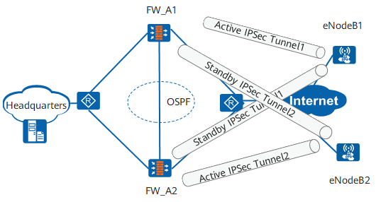
As shown in Figure 3, FW_A1 and FW_A2 work in load sharing mode. eNodeB1 and eNodeB2 each set up active and standby IPSec tunnels with FW_A1 and FW_A2.
The IPSec tunnel setup process is as follows:- The same IP addresses IP_1 and IP_2 are configured on physical interfaces connecting FW_A1 and FW_A2 to the downstream router.
- eNodeB1 uses IP_1 as the peer address to set up active IPSec Tunnel1 and standby IPSec Tunnel1 with FW_A1 and FW_A2, respectively. eNodeB2 uses IP_2 as the peer address to set up active IPSec Tunnel2 and standby IPSec Tunnel2 with FW_A2 and FW_A1, respectively.
- When FW_A1 and FW_A2 are running properly, eNodeB1 forwards user traffic to the headquarters through active IPSec Tunnel1, and eNodeB2 forwards user traffic to the headquarters through active IPSec Tunnel2.
- If FW_A1 is faulty, eNodeB1 forwards user traffic to the headquarters through standby IPSec Tunnel1 connected to FW_A2. Similarly, if FW_A2 is faulty, eNodeB2 forwards user traffic to the headquarters through standby IPSec Tunnel2 connected to FW_A1.
IPSec gateways are configured to work in load sharing mode and are connected to upstream and downstream switches, and IPSec tunnels are backed up.
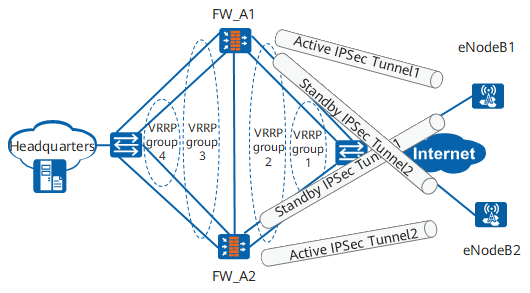
As shown in Figure 4, FW_A1 and FW_A2 work in load sharing mode. eNodeB1 and eNodeB2 each set up active and standby IPSec tunnels with FW_A1 and FW_A2.
The IPSec tunnel setup process is as follows:
- VRRP group 1 containing FW_A1 and FW_A2 is created. eNodeB1 uses the virtual IP address of VRRP group 1 as the peer address to set up active IPSec Tunnel1 and standby IPSec Tunnel1 with FW_A1 and FW_A2, respectively.
- VRRP group 2 containing FW_A1 and FW_A2 is created. eNodeB2 uses the virtual IP address of VRRP group 2 as the peer address to set up active IPSec Tunnel2 and standby IPSec Tunnel2 with FW_A2 and FW_A1, respectively.
- When FW_A1 and FW_A2 are running properly, eNodeB1 forwards user traffic to the headquarters through active IPSec Tunnel1, and eNodeB2 forwards user traffic to the headquarters through active IPSec Tunnel2.
- If FW_A1 is faulty, eNodeB1 forwards user traffic to the headquarters through standby IPSec Tunnel1 connected to FW_A2. Similarly, if FW_A2 is faulty, eNodeB2 forwards user traffic to the headquarters through standby IPSec Tunnel2 connected to FW_A1.