Link Redundancy
To improve network reliability, an enterprise connects a branch network to the headquarters network through two or more links. When a link fails, services are immediately switched to another link. The device provides two redundancy modes: active/standby IPSec links and IPSec multi-link.
Active and Standby IPSec Links
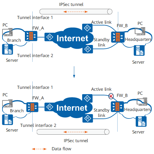
In Figure 1, FW_A connects to FW_B through active and standby links. Two tunnel interfaces are created on FW_A and they borrow the IP address of the same physical interface. Different IPSec policies are applied to the two tunnel interfaces to create active and standby IPSec tunnels. Different IPSec policies are applied to two physical interfaces on FW_B. When the active link fails, traffic is switched to the standby link. A new IPSec tunnel is established on the standby link, and the old IPSec tunnel is deleted.
IPSec Multi-link
In Figure 2, FW_A connects to FW_B through active and standby links. An IPSec tunnel is established between a physical interface of FW_A and a tunnel interface of FW_B. On FWB, traffic is processed by IPSec on the tunnel interface and sent out by a physical interface according to the routing table. When the active link fails, the corresponding route is unreachable and traffic is switched to the standby link. Re-negotiation is not required for the IPSec tunnel, so traffic can be rapidly switched.
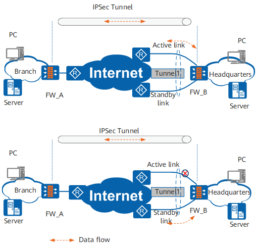
A tunnel interface can implement multi-link redundancy. This mode is simpler and switches traffic faster than the active/standby links.

In the scenario where an IPSec gateway is connected to different ISP networks or the same ISP network but the active and standby links are connected to different access routers of the same ISP network across LANs or areas, if the active link becomes faulty, the device on the standby link may discard the IPSec packets whose source address belongs to a different ISP network or access router. Therefore, before configuring link redundancy, check whether active/standby link switching is allowed in the actual network environment.