CLI: Example for Configuring Tunnel Interfaces Between Gateways to Implement IPSec Tunnel Redundancy
Networking Requirements
As shown in Figure 1, FW_A connects network A to the Internet and FW_B connects network B to the Internet.
Multiple reachable routes exist between FW_A and FW_B.
The networking requirements are as follows:
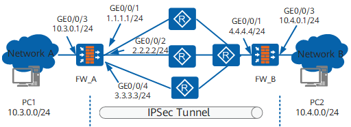
Data Plan
Item |
Data |
|---|---|
FW_A |
Interface number: GigabitEthernet 0/0/3 IP address: 10.3.0.1/24 Security zone: Trust |
Interface number: GigabitEthernet 0/0/1 IP address: 1.1.1.1/24 Security zone: Untrust |
|
Interface number: GigabitEthernet 0/0/2 IP address: 2.2.2.2/24 Security zone: Untrust |
|
Interface number: GigabitEthernet 0/0/4 IP address: 3.3.3.3/24 Security zone: Untrust |
|
Tunnel interface Interface number: Tunnel 0 IP address: 1.1.0.2/24 Security zone: Untrust |
|
IPSec configuration Peer IP address: 4.4.4.4 Authentication type: pre-shared key Pre-shared key: Test!123 Local ID type: IP address Peer ID type: any |
|
FW_B |
Interface number: GigabitEthernet 0/0/1 IP address: 4.4.4.4/24 Security zone: Untrust |
Interface number: GigabitEthernet 0/0/3 IP address: 10.4.0.1/24 Security zone: Trust |
|
IPSec configuration Peer IP address: 1.1.0.2 Authentication type: pre-shared key Pre-shared key: Test!123 Local ID type: IP address Peer ID type: any |
Procedure
- Configure FW_A.
- Add the tunnel interface to a security zone.
[FW_A] firewall zone untrust
[FW_A-zone-untrust] add interface tunnel 0
[FW_A-zone-untrust] quit

The tunnel interface can be added to other security zones, but you must configure packet filtering to permit interzone traffic.
- Configure interzone security policies.
# Configure the security policies between the Trust and Untrust zones to permit the interzone traffic.
[FW_A] security-policy
[FW_A-policy-security] rule name policy_ipsec_1
[FW_A-policy-security-rule-policy_ipsec_1] source-zone trust
[FW_A-policy-security-rule-policy_ipsec_1] destination-zone untrust
[FW_A-policy-security-rule-policy_ipsec_1] source-address 10.3.0.0 24
[FW_A-policy-security-rule-policy_ipsec_1] destination-address 10.4.0.0 24
[FW_A-policy-security-rule-policy_ipsec_1] action permit
[FW_A-policy-security-rule-policy_ipsec_1] quit
[FW_A-policy-security] rule name policy_ipsec_2
[FW_A-policy-security-rule-policy_ipsec_2] source-zone untrust
[FW_A-policy-security-rule-policy_ipsec_2] destination-zone trust
[FW_A-policy-security-rule-policy_ipsec_2] source-address 10.4.0.0 24
[FW_A-policy-security-rule-policy_ipsec_2] destination-address 10.3.0.0 24
[FW_A-policy-security-rule-policy_ipsec_2] action permit
[FW_A-policy-security-rule-policy_ipsec_2] quit
# Configure the security policies between the Local and Untrust zones to ensure tunnel establishment.
The Local-Untrust interzone policy controls whether IKE negotiation packets can pass through the FW. This policy can use the source and destination addresses, protocol, or port as the matching condition. In this example, the source and destination addresses are used as the matching condition. To use the protocol or port as the matching condition, you need to enable ESP and port 500 for UDP (port 4500 also in NAT traversal scenarios).
[FW_A-policy-security] rule name policy_ipsec_3
[FW_A-policy-security-rule-policy_ipsec_3] source-zone local
[FW_A-policy-security-rule-policy_ipsec_3] destination-zone untrust
[FW_A-policy-security-rule-policy_ipsec_3] source-address 1.1.1.1 32
[FW_A-policy-security-rule-policy_ipsec_3] source-address 2.2.2.2 32
[FW_A-policy-security-rule-policy_ipsec_3] source-address 3.3.3.3 32
[FW_A-policy-security-rule-policy_ipsec_3] source-address 1.1.0.2 32
[FW_A-policy-security-rule-policy_ipsec_3] destination-address 4.4.4.4 32
[FW_A-policy-security-rule-policy_ipsec_3] action permit
[FW_A-policy-security-rule-policy_ipsec_3] quit
[FW_A-policy-security] rule name policy_ipsec_4
[FW_A-policy-security-rule-policy_ipsec_4] source-zone untrust
[FW_A-policy-security-rule-policy_ipsec_4] destination-zone local
[FW_A-policy-security-rule-policy_ipsec_4] source-address 4.4.4.4 32
[FW_A-policy-security-rule-policy_ipsec_4] destination-address 1.1.1.1 32
[FW_A-policy-security-rule-policy_ipsec_4] destination-address 2.2.2.2 32
[FW_A-policy-security-rule-policy_ipsec_4] destination-address 3.3.3.3 32
[FW_A-policy-security-rule-policy_ipsec_4] destination-address 1.1.0.2 32
[FW_A-policy-security-rule-policy_ipsec_4] action permit
[FW_A-policy-security-rule-policy_ipsec_4] quit
[FW_A-policy-security] quit
- Configure an IKE peer.
[FW_A] ike peer b
[FW_A-ike-peer-b] ike-proposal 10
[FW_A-ike-peer-b] remote-address 4.4.4.4
[FW_A-ike-peer-b] pre-shared-key Test!123
[FW_A-ike-peer-b] quit
The FW supports IKEv1 and IKEv2, but uses IKEv2 by default. If the peer does not support IKEv2, you must disable IKEv2 to use IKEv1.
The peer IP address is the WAN interface IP address of FW_B.
The pre-shared key must be the same on both endpoints.
- Add the tunnel interface to a security zone.
- Configure FW_B.
- Configure interzone security policies.
# Configure the security policies between the Trust and Untrust zones to permit the interzone traffic.
[FW_B] security-policy
[FW_B-policy-security] rule name policy_ipsec_1
[FW_B-policy-security-rule-policy_ipsec_1] source-zone trust
[FW_B-policy-security-rule-policy_ipsec_1] destination-zone untrust
[FW_B-policy-security-rule-policy_ipsec_1] source-address 10.4.0.0 24
[FW_B-policy-security-rule-policy_ipsec_1] destination-address 10.3.0.0 24
[FW_B-policy-security-rule-policy_ipsec_1] action permit
[FW_B-policy-security-rule-policy_ipsec_1] quit
[FW_B-policy-security] rule name policy_ipsec_2
[FW_B-policy-security-rule-policy_ipsec_2] source-zone untrust
[FW_B-policy-security-rule-policy_ipsec_2] destination-zone trust
[FW_B-policy-security-rule-policy_ipsec_2] source-address 10.3.0.0 24
[FW_B-policy-security-rule-policy_ipsec_2] destination-address 10.4.0.0 24
[FW_B-policy-security-rule-policy_ipsec_2] action permit
[FW_B-policy-security-rule-policy_ipsec_2] quit
# Configure the security policies between the Local and Untrust zones to ensure tunnel establishment.
The Local-Untrust interzone policy controls whether IKE negotiation packets can pass through the FW. This policy can use the source and destination addresses, protocol, or port as the matching condition. In this example, the source and destination addresses are used as the matching condition. To use the protocol or port as the matching condition, you need to enable ESP and port 500 for UDP (port 4500 also in NAT traversal scenarios).
[FW_B-policy-security] rule name policy_ipsec_3
[FW_B-policy-security-rule-policy_ipsec_3] source-zone local
[FW_B-policy-security-rule-policy_ipsec_3] destination-zone untrust
[FW_B-policy-security-rule-policy_ipsec_3] source-address 4.4.4.4 32
[FW_B-policy-security-rule-policy_ipsec_3] destination-address 1.1.1.1 32
[FW_B-policy-security-rule-policy_ipsec_3] destination-address 2.2.2.2 32
[FW_B-policy-security-rule-policy_ipsec_3] destination-address 3.3.3.3 32
[FW_B-policy-security-rule-policy_ipsec_3] destination-address 1.1.0.2 32
[FW_B-policy-security-rule-policy_ipsec_3] action permit
[FW_B-policy-security-rule-policy_ipsec_3] quit
[FW_B-policy-security] rule name policy_ipsec_4
[FW_B-policy-security-rule-policy_ipsec_4] source-zone untrust
[FW_B-policy-security-rule-policy_ipsec_4] destination-zone local
[FW_B-policy-security-rule-policy_ipsec_4] source-address 1.1.1.1 32
[FW_B-policy-security-rule-policy_ipsec_4] source-address 2.2.2.2 32
[FW_B-policy-security-rule-policy_ipsec_4] source-address 3.3.3.3 32
[FW_B-policy-security-rule-policy_ipsec_4] source-address 1.1.0.2 32
[FW_B-policy-security-rule-policy_ipsec_4] destination-address 4.4.4.4 32
[FW_B-policy-security-rule-policy_ipsec_4] action permit
[FW_B-policy-security-rule-policy_ipsec_4] quit
[FW_B-policy-security] quit
- Configure an IKE peer named a.
[FW_B] ike peer a
[FW_B-ike-peer-a] ike-proposal 10
[FW_B-ike-peer-a] remote-address 1.1.0.2
[FW_B-ike-peer-a] pre-shared-key Test!123
[FW_B-ike-peer-a] quit
The FW supports IKEv1 and IKEv2, but uses IKEv2 by default. If the peer does not support IKEv2, you must disable IKEv2 to use IKEv1.
The pre-shared key must be the same on both endpoints.
- Configure interzone security policies.
Verification
After all configurations are complete, ping PC2 from PC1. If the configurations are correct, PC1 can ping PC2. If information in steps 2, 3, and 4 is displayed, the data transmission between PC1 and PC2 is encapsulated by the IPSec tunnel.
On FW_A and FW_B, run the display ike sa command to display the established IKE SAs. Take FW_A as an example. If the following information is displayed, the IKE SAs are successfully established.
<FW_A> display ike sa
IKE SA information :
    Conn-ID     Peer            VPN   Flag(s)  Phase  RemoteType  RemoteID
  -----------------------------------------------------------------------------
    20002       4.4.4.4:500           RD|ST|A  v2:2   IP          4.4.4.4
    20001       4.4.4.4:500           RD|ST|A  v2:1   IP          4.4.4.4

  Number of IKE SA : 2
  -------------------------------------------------------------------------------

  Flag Description:
  RD--READY   ST--STAYALIVE   RL--REPLACED   FD--FADING   TO--TIMEOUT
  HRT--HEARTBEAT   LKG--LAST KNOWN GOOD SEQ NO.   BCK--BACKED UP
  M--ACTIVE   S--STANDBY   A--ALONE  NEG--NEGOTIATING
On FW_A and FW_B, run the display ipsec sa command to display the established IPSec SAs. Take FW_A as an example. If the following information is displayed, the IKE SAs are successfully established.
<FW_A> display ipsec sa =============================== Interface: Tunnel0 =============================== ----------------------------- IPSec policy name: "map1" Sequence number : 10 Acl group : 3000 Acl rule : 5 Mode : ISAKMP ----------------------------- Connection ID: 40002 Encapsulation mode: Tunnel Tunnel local : 1.1.0.2 Tunnel remote : 4.4.4.4 Flow source : 10.3.0.0/255.255.255.0 0/0 Flow destination : 10.4.0.0/255.255.255.0 0/0 [Outbound ESP SAs] SPI: 228290096 (0xd9b6e30) Proposal: ESP-ENCRYPT-AES-256 SHA2-256-128 SA remaining key duration (bytes/sec): 1887436464/3549 Max sent sequence-number: 5 UDP encapsulation used for NAT traversal: N SA decrypted packets (number/kilobytes): 4/0 [Inbound ESP SAs] SPI: 38742361 (0x24f2959) Proposal: ESP-ENCRYPT-AES-256 SHA2-256-128 SA remaining key duration (bytes/sec): 1887436464/3549 Max received sequence-number: 4 UDP encapsulation used for NAT traversal: N SA decrypted packets (number/kilobytes): 4/0 Anti-replay : Enable Anti-replay window size: 1024- Run the display ipsec statistics command to display the encrypted data. The output indicates that data transmission is encrypted. Take FW_A as an example.
<FW_A>display ipsec statistics
  the security packet statistics:
    input/output security packets: 4/4
    input/output security bytes: 400/400
    input/output dropped security packets: 0/0
    the encrypt packet statistics
      send sae:0, recv sae:0, send err:0
      local cpu:0, other cpu:0, recv other cpu:0
      intact packet:0, first slice:0, after slice:0
    the decrypt packet statistics
      send sae:0, recv sae:0, send err:0
      local cpu:0, other cpu:0, recv other cpu:0
      reass  first slice:0, after slice:0, len err:0
    dropped security packet detail:
      no enough memory: 0, too long: 0
      can't find SA: 0, wrong SA: 0
      authentication: 0, replay: 0
      front recheck: 0, after recheck: 0
      exceed byte limit: 0, exceed packet limit: 0
      change cpu enc: 0, dec change cpu: 0
      change datachan: 0, fib search: 0
      rcv enc(dec) form sae said err: 0, 0
      send port: 0, output l3: 0, l2tp input: 0
  negotiate about packet statistics:
    IP packet  ok:0, err:0, drop:0
    IP rcv other cpu   to ike:0, drop:0
    IKE packet inbound   ok:0, err:0
    IKE packet outbound  ok:0, err:0
    SoftExpr:0, HardExpr:0, DPDOper:0, SwapSa:0
    ModpCnt: 0, SaeSucc: 0, SoftwareSucc: 0
Disable GigabitEthernet 0/0/1, GigabitEthernet 0/0/2, or GigabitEthernet 0/0/4 of FW_A to verify that the IPSec tunnel is not torn down. This configuration ensures link redundancy.
The verification procedure is as follows:
- Run the display ike sa and display ipsec sa commands. The SAs still exist.
- Network A and network B can communicate. Run the display ipsec statistics command. The number of encrypted packets increases.
Configuration Files
-
#
 sysname FW_A
#
acl number 3000
 rule 5 permit ip source 10.3.0.0 0.0.0.255 destination 10.4.0.0 0.0.0.255
#
ipsec proposal tran1
 esp authentication-algorithm sha2-256
 esp encryption-algorithm aes-256
#
ike proposal 10
  encryption-algorithm aes-256
  dh group14
  authentication-algorithm sha2-256
  authentication-method pre-share
  integrity-algorithm hmac-sha2-256
  prf hmac-sha2-256
#
ike peer b
 pre-shared-key %^%#&Q%d(^GJj>jN}+S:;EEXkGD^%^%#
 ike-proposal 10
 remote-address 4.4.4.4
#
ipsec policy map1 10 isakmp
 security acl 3000
 ike-peer b
 proposal tran1
#
interface GigabitEthernet0/0/3
 undo shutdown
 ip address 10.3.0.1 255.255.255.0
#
interface GigabitEthernet0/0/1
 undo shutdown
 ip address 1.1.1.1 255.255.255.0
#
interface GigabitEthernet0/0/2
 undo shutdown
 ip address 2.2.2.2 255.255.255.0
#
interface GigabitEthernet0/0/4
 undo shutdown
 ip address 3.3.3.3 255.255.255.0
#
interface Tunnel0
 ip address 1.1.0.2 255.255.255.0
 tunnel-protocol ipsec
 ipsec policy map1
#
firewall zone trust
 set priority 85
 add interface GigabitEthernet0/0/3
#
firewall zone untrust
 set priority 5
 add interface Tunnel0
 add interface GigabitEthernet0/0/1
 add interface GigabitEthernet0/0/2
 add interface GigabitEthernet0/0/4
#
 ip route-static 10.4.0.0 255.255.255.0 tunnel 0
 ip route-static 4.4.4.4 32 1.1.1.254
 ip route-static 4.4.4.4 32 2.2.2.254
 ip route-static 4.4.4.4 32 3.3.3.254

#
security-policy
  rule name policy_ipsec_1
    source-zone trust
    destination-zone untrust
    source-address 10.3.0.0 255.255.255.0
    destination-address 10.4.0.0 255.255.255.0
    action permit
  rule name policy_ipsec_2
    source-zone untrust
    destination-zone trust
    source-address 10.4.0.0 255.255.255.0
    destination-address 10.3.0.0 255.255.255.0
    action permit
  rule name policy_ipsec_3
    source-zone local
    destination-zone untrust
    source-address 1.1.1.1 255.255.255.255
    source-address 2.2.2.2 255.255.255.255
    source-address 3.3.3.3 255.255.255.255
    source-address 1.1.0.2 255.255.255.255
    destination-address 4.4.4.4 255.255.255.255
    action permit
  rule name policy_ipsec_4
    source-zone untrust
    destination-zone local
    source-address 4.4.4.4 255.255.255.255
    destination-address 1.1.1.1 255.255.255.255
    destination-address 2.2.2.2 255.255.255.255
    destination-address 3.3.3.3 255.255.255.255
    destination-address 1.1.0.2 255.255.255.255
    action permit
#
return
-
#
 sysname FW_B
#
acl number 3000
 rule 5 permit ip source 10.4.0.0 0.0.0.255 destination 10.3.0.0 0.0.0.255
#
ipsec proposal tran1
 esp authentication-algorithm sha2-256
 esp encryption-algorithm aes-256
#
ike proposal 10
  encryption-algorithm aes-256
  dh group14
  authentication-algorithm sha2-256
  authentication-method pre-share
  integrity-algorithm hmac-sha2-256
  prf hmac-sha2-256
#
ike peer a
 pre-shared-key %^%#w^t!:ML@w;{oqPXFYt<U7c-S%^%#
 ike-proposal 10
 remote-address 1.1.0.2
#
ipsec policy map1 10 isakmp
 security acl 3000
 ike-peer a
 proposal tran1
#
interface GigabitEthernet0/0/3
 undo shutdown
 ip address 10.4.0.1 255.255.255.0
#
interface GigabitEthernet0/0/1
 undo shutdown
 ip address 4.4.4.4 255.255.255.0
 ipsec policy map1
#
firewall zone trust
 set priority 85
 add interface GigabitEthernet0/0/3
#
firewall zone untrust
 set priority 5
 add interface GigabitEthernet0/0/1
#
 ip route-static 10.3.0.0 255.255.255.0 4.4.4.254
 ip route-static 1.1.0.2 255.255.255.255 4.4.4.254
#
security-policy
  rule name policy_ipsec_1
    source-zone trust
    destination-zone untrust
    source-address 10.4.0.0 255.255.255.0
    destination-address 10.3.0.0 255.255.255.0
    action permit
  rule name policy_ipsec_2
    source-zone untrust
    destination-zone trust
    source-address 10.3.0.0 255.255.255.0
    destination-address 10.4.0.0 255.255.255.0
    action permit
  rule name policy_ipsec_3
    source-zone local
    destination-zone untrust
    source-address 4.4.4.4 255.255.255.255
    destination-address 1.1.1.1 255.255.255.255
    destination-address 2.2.2.2 255.255.255.255
    destination-address 3.3.3.3 255.255.255.255
    destination-address 1.1.0.2 255.255.255.255
    action permit
  rule name policy_ipsec_4
    source-zone untrust
    destination-zone local
    source-address 1.1.1.1 255.255.255.255
    source-address 2.2.2.2 255.255.255.255
    source-address 3.3.3.3 255.255.255.255
    source-address 1.1.0.2 255.255.255.255
    destination-address 4.4.4.4 255.255.255.255
    action permit
#
return