CLI: Example for Configuring IPSec Gateway Redundancy
Networking Requirements
As shown in Figure 1, the FW_A and FW_B connects the headquarters to the Internet, and FW_C connects the branch office to the headquarters. An IPSec tunnel is required between the headquarters and branch office to secure data transmission. The company has multiple branch offices. This example describes only one branch office, whose gateway is FW_C. To improve network reliability, FW_A and FW_B are configured to work in active/standby mode for hot standby. The upstream and downstream devices of the gateways are switches.
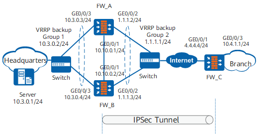
Data Plan
Item |
FW_A |
FW_B |
FW_C |
|---|---|---|---|
Interface |
Interface number: GigabitEthernet 0/0/1 IP address: 10.10.0.1/24 Security zone: DMZ |
Interface number: GigabitEthernet 0/0/1 IP address: 10.10.0.2/24 Security zone: DMZ |
Interface number: GigabitEthernet 0/0/1 IP address: 4.4.4.4/24 Security zone: Untrust |
Interface number: GigabitEthernet 0/0/2 IP address: 1.1.1.2/24 VRRP group 2 IP address: 1.1.1.1/24 Security zone: Untrust |
Interface number: GigabitEthernet 0/0/2 IP address: 1.1.1.3/24 VRRP group 2 IP address: 1.1.1.1/24 Security zone: Untrust |
Interface number: GigabitEthernet 0/0/3 IP address: 10.4.1.1/24 Security zone: Trust |
|
Interface number: GigabitEthernet 0/0/3 IP address: 10.3.0.3/24 VRRP group 1 IP address: 10.3.0.2/24 Security zone: Trust |
Interface number: GigabitEthernet 0/0/3 IP address: 10.3.0.4/24 VRRP group 1 IP address: 10.3.0.2/24 Security zone: Trust |
- |
|
IPSec configuration |
IPSec policy type: policy template Pre-shared key: Admin@123 Local ID type: IP address Peer ID type: IP address |
IPSec policy type: policy template Pre-shared key: Admin@123 Local ID type: IP address Peer ID type: IP address |
IPSec policy type: ISAKMP Pre-shared key: Admin@123 Local ID type: IP address Peer ID type: IP address |
Configuration Roadmap
- Configure hot standby on FW_A and FW_B.
- Configure security policies and IPSec services on FW_A.
After the hot standby function of FW_A and FW_B is enabled, the security policies and IPSec services on FW_A will be automatically backed up to FW_B.
- Configure FW_C to establish an IPSec tunnel.
Procedure
- Configure hot standby on FW_A (Headquarters) and FW_B (Headquarters).
- Configure security policies and IPSec services on FW_A.
- Configure security policies.
Configure Trust-Untrust interzone policies to allow original and decapsulated packets to pass through FW_A.
[FW_A] security-policy
[FW_A-policy-security] rule name policy_ipsec_1
[FW_A-policy-security-rule-policy_ipsec_1] source-zone trust
[FW_A-policy-security-rule-policy_ipsec_1] destination-zone untrust
[FW_A-policy-security-rule-policy_ipsec_1] source-address 10.3.0.0 24
[FW_A-policy-security-rule-policy_ipsec_1] destination-address 10.4.1.0 24
[FW_A-policy-security-rule-policy_ipsec_1] action permit
[FW_A-policy-security-rule-policy_ipsec_1] quit
[FW_A-policy-security] rule name policy_ipsec_2
[FW_A-policy-security-rule-policy_ipsec_2] source-zone untrust
[FW_A-policy-security-rule-policy_ipsec_2] destination-zone trust
[FW_A-policy-security-rule-policy_ipsec_2] source-address 10.4.1.0 24
[FW_A-policy-security-rule-policy_ipsec_2] destination-address 10.3.0.0 24
[FW_A-policy-security-rule-policy_ipsec_2] action permit
[FW_A-policy-security-rule-policy_ipsec_2] quit
Configure Local-Untrust interzone policies to allow IKE negotiation packets to pass through FW_A.

The Local-Untrust interzone policy controls whether IKE negotiation packets can pass through the FW. This policy can use the source and destination addresses, protocol, or port as the matching condition. In this example, the source and destination addresses are used as the matching condition. To use the protocol or port as the matching condition, you need to enable ESP and port 500 for UDP (port 4500 also in NAT traversal scenarios).
[FW_A-policy-security] rule name policy_ipsec_3
[FW_A-policy-security-rule-policy_ipsec_3] source-zone local
[FW_A-policy-security-rule-policy_ipsec_3] destination-zone untrust
[FW_A-policy-security-rule-policy_ipsec_3] source-address 1.1.1.1 32
[FW_A-policy-security-rule-policy_ipsec_3] destination-address 4.4.4.4 32
[FW_A-policy-security-rule-policy_ipsec_3] action permit
[FW_A-policy-security-rule-policy_ipsec_3] quit
[FW_A-policy-security] rule name policy_ipsec_4
[FW_A-policy-security-rule-policy_ipsec_4] source-zone untrust
[FW_A-policy-security-rule-policy_ipsec_4] destination-zone local
[FW_A-policy-security-rule-policy_ipsec_4] source-address 4.4.4.4 32
[FW_A-policy-security-rule-policy_ipsec_4] destination-address 1.1.1.1 32
[FW_A-policy-security-rule-policy_ipsec_4] action permit
[FW_A-policy-security-rule-policy_ipsec_4] quit
[FW_A-policy-security] quit
- Configure security policies.
- Configure routes on FW_B.
After the hot standby function of FW_A and FW_B is enabled, the security policies and IPSec services on FW_A will be automatically backed up to FW_B. However, route configuration on FW_A is not synchronized to FW_B. Therefore, you need to manually configure routes on FW_B.
# Create a default route with next hop 1.1.1.254.HRP_S[FW_B] ip route-static 0.0.0.0 0.0.0.0 1.1.1.254# Create a static route to the branch intranet with next hop 1.1.1.254.HRP_S[FW_B] ip route-static 10.4.1.0 255.255.255.0 1.1.1.254 - Configure FW_C (Branch).
- Configure security policies.
Configure Trust-Untrust interzone policies to allow original and decapsulated packets to pass through FW_C.
[FW_C] security-policy
[FW_C-policy-security] rule name policy_ipsec_1
[FW_C-policy-security-rule-policy_ipsec_1] source-zone trust
[FW_C-policy-security-rule-policy_ipsec_1] destination-zone untrust
[FW_C-policy-security-rule-policy_ipsec_1] source-address 10.4.1.0 24
[FW_C-policy-security-rule-policy_ipsec_1] destination-address 10.3.0.0 24
[FW_C-policy-security-rule-policy_ipsec_1] action permit
[FW_C-policy-security-rule-policy_ipsec_1] quit
[FW_C-policy-security] rule name policy_ipsec_2
[FW_C-policy-security-rule-policy_ipsec_2] source-zone untrust
[FW_C-policy-security-rule-policy_ipsec_2] destination-zone trust
[FW_C-policy-security-rule-policy_ipsec_2] source-address 10.3.0.0 24
[FW_C-policy-security-rule-policy_ipsec_2] destination-address 10.4.1.0 24
[FW_C-policy-security-rule-policy_ipsec_2] action permit
[FW_C-policy-security-rule-policy_ipsec_2] quit
Configure Local-Untrust interzone policies to allow IKE negotiation packets to pass through FW_C.
The Local-Untrust interzone policy controls whether IKE negotiation packets can pass through the FW. This policy can use the source and destination addresses, protocol, or port as the matching condition. In this example, the source and destination addresses are used as the matching condition. To use the protocol or port as the matching condition, you need to enable ESP and port 500 for UDP (port 4500 also in NAT traversal scenarios).
[FW_C-policy-security] rule name policy_ipsec_3
[FW_C-policy-security-rule-policy_ipsec_3] source-zone local
[FW_C-policy-security-rule-policy_ipsec_3] destination-zone untrust
[FW_C-policy-security-rule-policy_ipsec_3] source-address 4.4.4.4 32
[FW_C-policy-security-rule-policy_ipsec_3] destination-address 1.1.1.1 32
[FW_C-policy-security-rule-policy_ipsec_3] action permit
[FW_C-policy-security-rule-policy_ipsec_3] quit
[FW_C-policy-security] rule name policy_ipsec_4
[FW_C-policy-security-rule-policy_ipsec_4] source-zone untrust
[FW_C-policy-security-rule-policy_ipsec_4] destination-zone local
[FW_C-policy-security-rule-policy_ipsec_4] source-address 1.1.1.1 32
[FW_C-policy-security-rule-policy_ipsec_4] destination-address 4.4.4.4 32
[FW_C-policy-security-rule-policy_ipsec_4] action permit
[FW_C-policy-security-rule-policy_ipsec_4] quit
[FW_C-policy-security] quit
- Configure FW_C to establish an IPSec tunnel.
- Configure an ACL to define the data flow to be protected.
[FW_C] acl 3000
[FW_C-acl-adv-3000] rule 5 permit ip source 10.4.1.0 0.0.0.255 destination 10.3.0.0 0.0.0.255
[FW_C-acl-adv-3000] quit
- Configure an IKE proposal numbered 10.
[FW_C] ike proposal 10
[FW_C-ike-proposal-10] dh group14
[FW_C-ike-proposal-10] quit
- Configure an IKE peer.
remote-address needs to be set to the virtual IP address of the peer devices that implement hot standby.
[FW_C] ike peer a
[FW_C-ike-peer-a] ike-proposal 10
[FW_C-ike-peer-a] remote-address 1.1.1.1
[FW_C-ike-peer-a] pre-shared-key Admin@123
[FW_C-ike-peer-a] quit
- Configure an IPSec proposal named tran1.
[FW_C] ipsec proposal tran1
[FW_C-ipsec-proposal-tran1] encapsulation-mode tunnel
[FW_C-ipsec-proposal-tran1] transform esp
[FW_C-ipsec-proposal-tran1] esp authentication-algorithm sha2-256
[FW_C-ipsec-proposal-tran1] esp encryption-algorithm aes-256
[FW_C-ipsec-proposal-tran1] quit
- Create an IPSec policy group named map1.
[FW_C] ipsec policy map1 10 isakmp
[FW_C-ipsec-policy-isakmp-map1-10] security acl 3000
[FW_C-ipsec-policy-isakmp-map1-10] proposal tran1
[FW_C-ipsec-policy-isakmp-map1-10] ike-peer a
[FW_C-ipsec-policy-isakmp-map1-10] quit
- Apply IPSec policy group map1 to outbound interface GigabitEthernet 0/0/1.
[FW_C] interface GigabitEthernet 0/0/1
[FW_C-GigabitEthernet0/0/1] ipsec policy map1
[FW_C-GigabitEthernet0/0/1] quit
- Configure an ACL to define the data flow to be protected.
- Configure security policies.
- Configure the switches.
Add the interfaces of each switch in Figure 1 to the same VLAN.
For configuration details, see the switch documents.
Verification
- Devices in the branch network 10.4.1.0/24 can successfully access the servers on the headquarters network 10.3.0.0/24.
Run the display ike sa and display ipsec sa commands on FW_A and FW_B. The command output shows that an IPSec tunnel has been established and tunnel backup succeeds.
- Disconnect GigabitEthernet 0/0/3 or GigabitEthernet 0/0/2 on FW_A. FW_B takes over services.
Configuration Files
-
#
 sysname FW_A
#
hrp interface GigabitEthernet0/0/1 remote 10.10.0.2
hrp enable
#
firewall zone trust
 set priority 85
 add interface GigabitEthernet0/0/3
#
firewall zone untrust
 set priority 5
 add interface GigabitEthernet0/0/2
#
firewall zone dmz
 set priority 50
 add interface GigabitEthernet0/0/1
#
acl 3000
 rule 5 permit ip source 10.3.0.0 0.0.0.255 destination 10.4.1.0 0.0.0.255
#
ipsec proposal tran1
 esp authentication-algorithm sha2-256
 esp encryption-algorithm aes-256
#
ike proposal 10
 encryption-algorithm aes-256
 dh group14
 authentication-algorithm sha2-256
 authentication-method pre-share
 integrity-algorithm hmac-sha2-256
 prf hmac-sha2-256
#
ike peer any
 ike-proposal 10
 pre-shared-key %^%#;;jt0m=SZ$38VaR"AICQBG.C%^%#
#
ipsec policy-template policy1 1
 security acl 3000
 proposal tran1
 ike-peer any
 tunnel local 1.1.1.1
#
ipsec policy map1 10 isakmp template policy1
#
interface GigabitEthernet0/0/1
 undo shutdown
 ip address 10.10.0.1 255.255.255.0
#
interface GigabitEthernet0/0/2
 undo shutdown
 ip address 1.1.1.2 255.255.255.0
 vrrp vrid 2 virtual-ip 1.1.1.1 24 active
 ipsec policy map1
#
interface GigabitEthernet0/0/3
 undo shutdown
 ip address 10.3.0.3 255.255.255.0
 vrrp vrid 1 virtual-ip 10.3.0.2 24 active
#
ip route-static 0.0.0.0 0.0.0.0 1.1.1.254
ip route-static 10.4.1.0 255.255.255.0 1.1.1.254
#
security-policy
  rule name policy_ipsec_1
    source-zone trust
    destination-zone untrust
    source-address 10.3.0.0 255.255.255.0
    destination-address 10.4.1.0 255.255.255.0
    action permit
  rule name policy_ipsec_2
    source-zone untrust
    destination-zone trust
    source-address 10.4.1.0 255.255.255.0
    destination-address 10.3.0.0 255.255.255.0
    action permit
  rule name policy_ipsec_3
    source-zone local
    destination-zone untrust
    source-address 1.1.1.1 255.255.255.255
    destination-address 4.4.4.4 255.255.255.255
    action permit
  rule name policy_ipsec_4
    source-zone untrust
    destination-zone local
    source-address 4.4.4.4 255.255.255.255
    destination-address 1.1.1.1 255.255.255.255
    action permit
#
return
-
#
 sysname FW_B
#
hrp interface GigabitEthernet0/0/1 remote 10.10.0.1
hrp enable
#
firewall zone trust
 set priority 85
 add interface GigabitEthernet0/0/3
#
firewall zone untrust
 set priority 5
 add interface GigabitEthernet0/0/2
#
firewall zone dmz
 set priority 50
 add interface GigabitEthernet0/0/1
#
acl 3000
 rule 5 permit ip source 10.3.0.0 0.0.0.255 destination 10.4.1.0 0.0.0.255
#
ipsec proposal tran1
 esp authentication-algorithm sha2-256
 esp encryption-algorithm aes-256
#
ike proposal 10
 encryption-algorithm aes-256
 dh group14
 authentication-algorithm sha2-256
 authentication-method pre-share
 integrity-algorithm hmac-sha2-256
 prf hmac-sha2-256
#
ike peer any
 ike-proposal 10
 pre-shared-key %^%#!6"\2KlkG@C|L+9HD*H#e>rj%^%#
#
ipsec policy-template policy1 1
 security acl 3000
 proposal tran1
 ike-peer any
 tunnel local 1.1.1.1
#
ipsec policy map1 10 isakmp template policy1
#
interface GigabitEthernet0/0/3
 undo shutdown
 ip address 10.3.0.4 255.255.255.0
 vrrp vrid 1 virtual-ip 10.3.0.2 24 standby
#
interface GigabitEthernet0/0/2
 undo shutdown
 ip address 1.1.1.3 255.255.255.0
 vrrp vrid 2 virtual-ip 1.1.1.1 24 standby
 ipsec policy map1
#
interface GigabitEthernet0/0/1
 undo shutdown
 ip address 10.10.0.2 255.255.255.0
#
interface GigabitEthernet0/0/1
 undo shutdown
 ip address 10.10.0.2 255.255.255.0
#
ip route-static 0.0.0.0 0.0.0.0 1.1.1.254
ip route-static 10.4.1.0 255.255.255.0 1.1.1.254
#
security-policy
  rule name policy_ipsec_1
    source-zone trust
    destination-zone untrust
    source-address 10.3.0.0 255.255.255.0
    destination-address 10.4.1.0 255.255.255.0
    action permit
  rule name policy_ipsec_2
    source-zone untrust
    destination-zone trust
    source-address 10.4.1.0 255.255.255.0
    destination-address 10.3.0.0 255.255.255.0
    action permit
  rule name policy_ipsec_3
    source-zone local
    destination-zone untrust
    source-address 1.1.1.1 255.255.255.255
    destination-address 4.4.4.4 255.255.255.255
    action permit
  rule name policy_ipsec_4
    source-zone untrust
    destination-zone local
    source-address 4.4.4.4 255.255.255.255
    destination-address 1.1.1.1 255.255.255.255
    action permit
#
return
-
#
 sysname FW_C
#
firewall zone trust
 set priority 85
 add interface GigabitEthernet0/0/3
#
firewall zone untrust
 set priority 5
 add interface GigabitEthernet0/0/1
#
acl 3000
 rule 5 permit ip source 10.4.1.0 0.0.0.255 destination 10.3.0.0 0.0.0.255
#
ipsec proposal tran1
 esp authentication-algorithm sha2-256
 esp encryption-algorithm aes-256
#
ike proposal 10
 encryption-algorithm aes-256
 dh group14
 authentication-algorithm sha2-256
 authentication-method pre-share
 integrity-algorithm hmac-sha2-256
 prf hmac-sha2-256
#
ike peer a
 pre-shared-key %^%#[,}r!W>aCD[_]~Ud-Q]~<g_D%^%#
 ike-proposal 10
 remote-address 1.1.1.1
#
ipsec policy map1 10 isakmp
 security acl 3000
 ike-peer a
 proposal tran1
#
interface GigabitEthernet0/0/3
 undo shutdown
 ip address 10.4.1.1 255.255.255.0
#
interface GigabitEthernet0/0/1
 undo shutdown
 ip address 4.4.4.4 255.255.255.0
 ipsec policy map1
#
ip route-static 0.0.0.0 0.0.0.0 4.4.4.254
ip route-static 10.3.0.0 255.255.255.0 4.4.4.254
#
security-policy
  rule name policy_ipsec_1
    source-zone trust
    destination-zone untrust
    source-address 10.4.1.0 255.255.255.0
    destination-address 10.3.0.0 255.255.255.0
    action permit
  rule name policy_ipsec_2
    source-zone untrust
    destination-zone trust
    source-address 10.3.0.0 255.255.255.0
    destination-address 10.4.1.0 255.255.255.0
    action permit
  rule name policy_ipsec_3
    source-zone local
    destination-zone untrust
    source-address 4.4.4.4 255.255.255.255
    destination-address 1.1.1.1 255.255.255.255
    action permit
  rule name policy_ipsec_4
    source-zone untrust
    destination-zone local
    source-address 1.1.1.1 255.255.255.255
    destination-address 4.4.4.4 255.255.255.255
    action permit
#
return