CLI: Example for Configuring IPSec Gateway Load Balancing With Routers Connected in the Upstream and Downstream
Context
As shown in Figure 1, the headquarters (HQ) connects to the Internet through the FW. FW_C and FW_D at the HQ work in load balancing mode. The service interfaces of the gateways work on Layer 3, the gateways are connected to routers in the upstream and downstream, and OSPF is running between the gateways and routers. The enterprise needs to set up IPSec tunnels between the HQ and branches. The traffic from FW_A is sent to the HQ through FW_C, and traffic from FW_B is sent to the HQ through FW_D. If FW_C or FW_D fails, the traffic served by the failed device is switched to the functioning device.
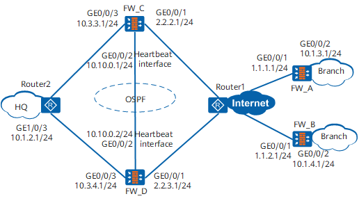
Data Planning
Item |
FW_A |
FW_B |
FW_C |
FW_D |
|
|---|---|---|---|---|---|
Interface |
GigabitEthernet 0/0/1 IP address: 1.1.1.1/24 Security zone: Untrust GigabitEthernet 0/0/2 IP address: 10.1.3.1/24 Security zone: Trust |
GigabitEthernet 0/0/1 IP address: 1.1.2.1/24 Security zone: Untrust GigabitEthernet 0/0/2 IP address: 10.1.4.1/24 Security zone: Trust |
GigabitEthernet 0/0/1 IP address: 2.2.2.1/24 Security zone: Untrust GigabitEthernet 0/0/2 IP address: 10.10.0.1/24 (heartbeat interface) Security zone: DMZ GigabitEthernet 0/0/3 IP address: 10.3.3.1/24 Security zone: Trust Tunnel1 IP address: 2.2.4.1/24 Security zone: Untrust Tunnel2 IP address: 2.2.5.1/24 Security zone: Untrust |
GigabitEthernet 0/0/1 IP address: 2.2.3.1/24 Security zone: Untrust GigabitEthernet 0/0/2 IP address: 10.10.0.2/24 (heartbeat interface) Security zone: DMZ GigabitEthernet 0/0/3 IP address: 10.3.4.1/24 Security zone: Trust Tunnel1 IP address: 2.2.4.1/24 Security zone: Untrust Tunnel2 IP address: 2.2.5.1/24 Security zone: Untrust |
|
IPSec policy type |
Non-template |
Non-template |
Non-template |
Non-template |
|
IPSec proposal |
Encapsulation mode |
Tunnel mode |
Tunnel mode |
Tunnel mode |
Tunnel mode |
Security protocol |
ESP |
ESP |
ESP |
ESP |
|
Authentication algorithm |
SHA2-256 |
SHA2-256 |
SHA2-256 |
SHA2-256 |
|
Encryption algorithm |
AES-256 |
AES-256 |
AES-256 |
AES-256 |
|
IKE peer |
Negotiation mode |
Main mode |
Main mode |
Main mode |
Main mode |
Pre-shared key |
Admin@123 |
Admin@123 |
Admin@123 |
Admin@123 |
|
Identity type |
IP |
IP |
IP |
IP |
|
Version |
v1 |
v1 |
v1 |
v1 |
|
Configuration Roadmap
- Configure FW_C and FW_D to work in load balancing mode.
- Create tunnel interfaces Tunnel1 and Tunnel2 on FW_C and FW_D. The IP address of interface Tunnel1 is the same on the two devices, and that of interface Tunnel2 is the same on the two devices. Interface Tunnel1 on FW_C is used to set up a primary tunnel with FW_A, and interface Tunnel1 on FW_D is used to set up a backup tunnel with FW_A. Similarly, interface Tunnel2 on FW_D is used to set up a primary tunnel with FW_B, and interface Tunnel2 on FW_C is used to set up a backup tunnel with FW_B. Then, FW_A and FW_B each has two IPSec tunnels, one with FW_C and the other with FW_D. When FW_C and FW_D are both normal, FW_A and FW_B sends traffic to the HQ via their primary tunnels. If FW_C or FW_D fails, FW_A or FW_B switches the IPSec traffic to the backup tunnel.
- Configure routing policies on FW_C and FW_D to change route priority when the device state changes. When the state of the two devices is normal, the traffic from the HQ to FW_A is sent through FW_C and the traffic from the HQ to FW_B is sent via FW_D. If, for example, FW_C fails, the traffic from the HQ to FW_A and FW_B is sent through FW_D.
- Apply the IPSec policies on the public network interfaces of FW_A and FW_B to set up IPSec tunnels with FW_C and FW_D.
Procedure
- Configure the HQ FWs.
- Configure OSPF routes.
To ensure that the traffic sent from FW_A to the HQ is transmitted along the path FWA -> Router1 -> FW_C -> Router2 and the traffic from FW_B to the HQ along the path FW_B -> Router1 -> FW_D -> Router2, configure routing policies on FW_C and FW_D to control routing information of Router1 and Router2.
When FW_C and FW_D are in load balancing mode, FW_C and FW_D advertise the direct routes destined for Tunnel1 to Router1 and advertise the private network routes (static routes) destined for FW_A to Router2. To forward different flows based on different routes, you need to control the direct routes and static routes advertised by FW_C and FW_D.
When FW_C works in load balancing mode, Router1 needs to send the traffic of FW_A to Tunnel1 of FW_C instead of Tunnel1 of FW_D. Therefore, when FW_C advertises the route destined for Tunnel1, FW_C needs to reduce the route cost by 10. When FW_D advertises the route destined for Tunnel1, FW_D needs to increase the route cost by 10. In this way, Router1 sends the traffic of FW_A to FW_C based on the route cost.
In addition, Router2 needs to send the reverse traffic of FW_A to FW_C instead of FW_D. Therefore, when FW_C advertises the private network route (static route) destined for FW_A, FW_C needs to reduce the route cost by 10. When FW_D advertises the private network route (static route) destined for FW_A, FW_D needs to increase the route cost by 10. In this way, Router2 sends the reverse traffic of FW_A to FW_C based on the route cost.
When FW_D is faulty and FW_C works in the active state, the OSPF cost value is adjusted through the active and standby states, so that all traffic of FW_A and FW_B can be send to FW_C for processing.
When FW_C is faulty and works in the standby state, the OSPF cost value is adjusted through the active and standby states, so that all traffic of FW_A and FW_B can be send to FW_D for processing.
Perform the following configurations on the HRP active device. The configurations will be automatically synchronized to the HRP standby device.
# Configure the ACLs used in routing policies.
HRP_M[FW_C] acl 2000
HRP_M[FW_C-acl-basic-2000] rule permit source 2.2.4.0 0.0.0.255
HRP_M[FW_C-acl-basic-2000] rule permit source 10.1.3.0 0.0.0.255
HRP_M[FW_C-acl-basic-2000] quit
HRP_M[FW_C] acl 2001
HRP_M[FW_C-acl-basic-2001] rule permit source 2.2.5.0 0.0.0.255
HRP_M[FW_C-acl-basic-2001] rule permit source 10.1.4.0 0.0.0.255
HRP_M[FW_C-acl-basic-2001] quit
Perform the following configurations on both the HRP active and standby devices.
# Configure a routing policy on the HRP active device.
HRP_M[FW_C] route-policy rp permit node 1
HRP_M[FW_C-route-policy] if-match acl 2000
HRP_M[FW_C-route-policy] apply cost - 10
HRP_M[FW_C-route-policy] quit
HRP_M[FW_C] route-policy rp permit node 2
HRP_M[FW_C-route-policy] if-match acl 2001
HRP_M[FW_C-route-policy] apply cost + 10
HRP_M[FW_C-route-policy] quit
HRP_M[FW_C] ospf 1
HRP_M[FW_C-ospf-1] import-route direct type 1 route-policy rp
HRP_M[FW_C-ospf-1] import-route static type 1 route-policy rp
HRP_M[FW_C-ospf-1] area 0.0.0.0
HRP_M[FW_C-ospf-1-area-0.0.0.0] network 10.3.3.0 0.0.0.255
HRP_M[FW_C-ospf-1-area-0.0.0.0] network 2.2.2.0 0.0.0.255
HRP_M[FW_C-ospf-1-area-0.0.0.0] quit
HRP_M[FW_C-ospf-1] quit
# Configure a routing policy on the HRP standby device.
HRP_S[FW_D] route-policy rp permit node 1
HRP_S[FW_D-route-policy] if-match acl 2000
HRP_S[FW_D-route-policy] apply cost + 10
HRP_S[FW_D-route-policy] quit
HRP_S[FW_D] route-policy rp permit node 2
HRP_S[FW_D-route-policy] if-match acl 2001
HRP_S[FW_D-route-policy] apply cost - 10
HRP_S[FW_D-route-policy] quit
HRP_S[FW_D] ospf 1
HRP_S[FW_D-ospf-1] import-route direct type 1 route-policy rp
HRP_S[FW_D-ospf-1] import-route static type 1 route-policy rp
HRP_S[FW_D-ospf-1] area 0.0.0.0
HRP_S[FW_D-ospf-1-area-0.0.0.0] network 10.3.4.0 0.0.0.255
HRP_S[FW_D-ospf-1-area-0.0.0.0] network 2.2.3.0 0.0.0.255
HRP_S[FW_D-ospf-1-area-0.0.0.0] quit
HRP_S[FW_D-ospf-1] quit

When configuring OSPF routes, configure correct inter-zone security policies to prevent normal routing protocol packets from being blocked.
- Configure OSPF routes.
- Configure FW in the branch.
The following provides the configuration of FW_A. The configuration of FW_B is similar to that of FW_A.
- Verify the configuration.
Enable the branch private network to ping the HQ private network to trigger IKE negotiation.
IKE negotiation succeeds. After an IPSec tunnel is established, data transmitted between the branches and HQ is encrypted.
- Run the display ipsec sa command on FW_A and FW_B to view IPSec SA information. The following example is the command output of FW_A. If information similar to the following is displayed, an IPSec SA has been established.
<FW_A> display ipsec sa brief
IPSec SA information:
   Src address      Dst address      SPI          VPN       Protocol          Algorithm
 ------------------------------------------------------------------------------------------------------
   1.1.1.1          2.2.4.1          194639781              ESP               E:AES-256 A:SHA2_256_128
   2.2.4.1          1.1.1.1          184618952              ESP               E:AES-256 A:SHA2_256_128

  Number of IPSec SA : 2
 ------------------------------------------------------------------------------------------------------
Check whether services are normal during an HRP switchover.
If the PCs can access HQ resources normally in the preceding three scenarios, service configurations are correct.
- When FW_A and FW_B are operational, enable the PCs connected to the two devices to access HQ resources. If so, the configurations are correct.
- Disable the interface of FW_C and then check whether the PCs can access HQ resources normally. If so, traffic can be switched from FW_C to FW_D.
- Enable the interface of FW_C, disable the interface of FW, and check whether the PCs can access HQ resources normally. If so, traffic can be switched from FW_D to FW_C.
Configuration Files
-
#
sysname FW_A
#
acl number 3000
 rule 5 permit ip source 10.1.3.0 0.0.0.255 destination 10.1.2.0 0.0.0.255
#
ipsec proposal tran1
 esp authentication-algorithm sha2-256
 esp encryption-algorithm aes-256
#
ike proposal 10
 encryption-algorithm aes-256
 dh group14
 authentication-algorithm sha2-256
 authentication-method pre-share
#
ike peer fw_c
 undo version 2
 pre-shared-key %^%#FkP$K2EKV+.vxTHdbEG/6>sQ-,<M[3iiJ1;od:pS%^%#
 ike-proposal 10
 remote-address 2.2.4.1
#
ipsec policy map1 10 isakmp
 security acl 3000
 ike-peer fw_c
 proposal tran1
#
interface GigabitEthernet0/0/1
 undo shutdown
 ip address 1.1.1.1 255.255.255.0
 ipsec policy map1
#
interface GigabitEthernet0/0/2
 undo shutdown
 ip address 10.1.3.1 255.255.255.0
#
firewall zone trust
 set priority 85
 add interface GigabitEthernet0/0/2
#
firewall zone untrust
 set priority 5
 add interface GigabitEthernet0/0/1
#
ip route-static 0.0.0.0 0.0.0.0 1.1.1.2
#
security-policy
 rule name 1
  source-zone trust
  destination-zone untrust
  source-address 10.1.3.0 mask 255.255.255.0
  destination-address 10.1.2.0 mask 255.255.255.0
  action permit
 rule name 2
  source-zone untrust
  destination-zone trust
  source-address 10.1.2.0 mask 255.255.255.0
  destination-address 10.1.3.0 mask 255.255.255.0
  action permit
 rule name 3
  source-zone local
  destination-zone untrust
  source-address 1.1.0.0 mask 255.255.0.0
  destination-address 2.2.0.0 mask 255.255.0.0
  action permit
 rule name 4
  source-zone untrust
  destination-zone local
  source-address 2.2.0.0 mask 255.255.0.0
  destination-address 1.1.0.0 mask 255.255.0.0
  action permit
#
return
-
#
sysname FW_B
#
acl number 3000
 rule 5 permit ip source 10.1.4.0 0.0.0.255 destination 10.1.2.0 0.0.0.255
#
ipsec proposal tran1
 esp authentication-algorithm sha2-256
 esp encryption-algorithm aes-256
#
ike proposal 10
 encryption-algorithm aes-256
 dh group14
 authentication-algorithm sha2-256
 authentication-method pre-share
#
ike peer fw_d
 undo version 2
 pre-shared-key %^%#FkP$K2EKV+.vxTHdbEG/6>sQ-,<M[3iiJ1;od:pS%^%#
 ike-proposal 10
 remote-address 2.2.5.1
#
ipsec policy map1 10 isakmp
 security acl 3000
 ike-peer fw_d
 proposal tran1
#
interface GigabitEthernet0/0/1
 undo shutdown
 ip address 1.1.2.1 255.255.255.0
 ipsec policy map1
#
interface GigabitEthernet0/0/2
 undo shutdown
 ip address 10.1.4.1 255.255.255.0
#
firewall zone trust
 set priority 85
 add interface GigabitEthernet0/0/2
#
firewall zone untrust
 set priority 5
 add interface GigabitEthernet0/0/1
#
ip route-static 0.0.0.0 0.0.0.0 1.1.2.2
#
security-policy
 rule name 1
  source-zone trust
  destination-zone untrust
  source-address 10.1.4.0 mask 255.255.255.0
  destination-address 10.1.2.0 mask 255.255.255.0
  action permit
 rule name 2
  source-zone untrust
  destination-zone trust
  source-address 10.1.2.0 mask 255.255.255.0
  destination-address 10.1.4.0 mask 255.255.255.0
  action permit
 rule name 3
  source-zone local
  destination-zone untrust
  source-address 1.1.0.0 mask 255.255.0.0
  destination-address 2.2.0.0 mask 255.255.0.0
  action permit
 rule name 4
  source-zone untrust
  destination-zone local
  source-address 2.2.0.0 mask 255.255.0.0
  destination-address 1.1.0.0 mask 255.255.0.0
  action permit
#
return
-
#
sysname FW_C
#
 hrp enable
 hrp interface GigabitEthernet0/0/2 remote 10.10.0.2
 hrp mirror session enable
 hrp track interface GigabitEthernet0/0/1
 hrp track interface GigabitEthernet0/0/3
#
acl number 2000
 rule 5 permit source 2.2.4.0 0.0.0.255
 rule 10 permit source 10.1.3.0 0.0.0.255
acl number 2001
 rule 5 permit source 2.2.5.0 0.0.0.255
 rule 10 permit source 10.1.4.0 0.0.0.255
acl number 3005
 rule 5 permit ip source 10.1.2.0 0.0.0.255 destination 10.1.3.0 0.0.0.255
acl number 3006
 rule 5 permit ip source 10.1.2.0 0.0.0.255 destination 10.1.4.0 0.0.0.255
#
ipsec proposal tran1
 esp authentication-algorithm sha2-256
 esp encryption-algorithm aes-256
#
ike proposal 10
 encryption-algorithm aes-256
 dh group14
 authentication-algorithm sha2-256
 authentication-method pre-share
#
ike peer fw_a
 undo version 2
 pre-shared-key %^%#4puFT<,]&I"YhN-2`NA,X&-!.aCh0/FwoKS:E{P"%^%#
 ike-proposal 10
 remote-address 1.1.1.1
ike peer fw_b
 undo version 2
 pre-shared-key %^%#8>ufTQw}T1-Ayd&b(!h7ev@U:1p/15#fEo+uggYO%^%#
 ike-proposal 10
 remote-address 1.1.2.1
#
ipsec policy map1 10 isakmp
 security acl 3005
 ike-peer fw_a
 proposal tran1
ipsec policy map2 10 isakmp
 security acl 3006
 ike-peer fw_b
 proposal tran1
#
interface GigabitEthernet0/0/1
 undo shutdown
 ip address 2.2.2.1 255.255.255.0
interface GigabitEthernet0/0/2
 undo shutdown
 ip address 10.10.0.1 255.255.255.0
interface GigabitEthernet0/0/3
 undo shutdown
 ip address 10.3.3.1 255.255.255.0
#
interface Tunnel 1
 ip address 2.2.4.1 255.255.255.0
 tunnel-protocol ipsec
 ipsec policy map1 master
#
interface Tunnel 2
 ip address 2.2.5.1 255.255.255.0
 tunnel-protocol ipsec
 ipsec policy map2 slave
#
firewall zone trust
 set priority 85
 add interface GigabitEthernet0/0/3
#
firewall zone untrust
 set priority 5
 add interface GigabitEthernet0/0/1
 add interface Tunnel 1
 add interface Tunnel 2
#
firewall zone dmz
 set priority 50
 add interface GigabitEthernet0/0/2
#
ospf 1
 import-route direct type 1 route-policy rp
 import-route static type 1 route-policy rp
 area 0.0.0.0
  network 2.2.2.0 0.0.0.255
  network 10.3.3.0 0.0.0.255
#
route-policy rp permit node 1
 if-match acl 2000
 apply cost - 10
#
route-policy rp permit node 2
 if-match acl 2001
 apply cost + 10
#
ip route-static 10.1.3.0 255.255.255.0 Tunnel1
ip route-static 10.1.4.0 255.255.255.0 Tunnel2
#
security-policy
 rule name 1
  source-zone untrust
  destination-zone trust
  source-address 10.1.3.0 mask 255.255.255.0
  source-address 10.1.4.0 mask 255.255.255.0
  destination-address 10.1.2.0 mask 255.255.255.0
  action permit
 rule name 2
  source-zone trust
  destination-zone untrust
  source-address 10.1.2.0 mask 255.255.255.0
  destination-address 10.1.3.0 mask 255.255.255.0
  destination-address 10.1.4.0 mask 255.255.255.0
  action permit
 rule name 3
  source-zone dmz
  source-zone local
  destination-zone dmz
  destination-zone local
  action permit
 rule name 4
  source-zone local
  destination-zone untrust
  source-address 2.2.0.0 mask 255.255.0.0
  destination-address 1.1.0.0 mask 255.255.0.0
  action permit
 rule name 5
  source-zone untrust
  destination-zone local
  source-address 1.1.0.0 mask 255.255.0.0
  destination-address 2.2.0.0 mask 255.255.0.0
  action permit
#
return
-
#
sysname FW_D
#
 hrp enable
 hrp interface GigabitEthernet0/0/2 remote 10.10.0.1
 hrp mirror session enable
 hrp track interface GigabitEthernet0/0/1
 hrp track interface GigabitEthernet0/0/3
#
acl number 2000
 rule 5 permit source 2.2.4.0 0.0.0.255
 rule 10 permit source 10.1.3.0 0.0.0.255
acl number 2001
 rule 5 permit source 2.2.5.0 0.0.0.255
 rule 10 permit source 10.1.4.0 0.0.0.255
acl number 3005
 rule 5 permit ip source 10.1.2.0 0.0.0.255 destination 10.1.3.0 0.0.0.255
acl number 3006
 rule 5 permit ip source 10.1.2.0 0.0.0.255 destination 10.1.4.0 0.0.0.255
#
ipsec proposal tran1
 esp authentication-algorithm sha2-256
 esp encryption-algorithm aes-256
#
ike proposal 10
 encryption-algorithm aes-256
 dh group14
 authentication-algorithm sha2-256
 authentication-method pre-share
#
ike peer fw_a
 undo version 2
 pre-shared-key %^%#4puFT<,]&I"YhN-2`NA,X&-!.aCh0/FwoKS:E{P"%^%#
 ike-proposal 10
 remote-address 1.1.1.1
ike peer fw_b
 undo version 2
 pre-shared-key %^%#8>ufTQw}T1-Ayd&b(!h7ev@U:1p/15#fEo+uggYO%^%#
 ike-proposal 10
 remote-address 1.1.2.1
#
ipsec policy map1 10 isakmp
 security acl 3005
 ike-peer fw_a
 proposal tran1
ipsec policy map2 10 isakmp
 security acl 3006
 ike-peer fw_b
 proposal tran1
#
interface GigabitEthernet0/0/1
 undo shutdown
 ip address 2.2.3.1 255.255.255.0
interface GigabitEthernet0/0/2
 undo shutdown
 ip address 10.10.0.2 255.255.255.0
interface GigabitEthernet0/0/3
 undo shutdown
 ip address 10.3.4.1 255.255.255.0
#
interface Tunnel 1
 ip address 2.2.4.1 255.255.255.0
 tunnel-protocol ipsec
 ipsec policy map1 slave
#
interface Tunnel 2
 ip address 2.2.5.1 255.255.255.0
 tunnel-protocol ipsec
 ipsec policy map2 master
#
firewall zone trust
 set priority 85
 add interface GigabitEthernet0/0/3
#
firewall zone untrust
 set priority 5
 add interface GigabitEthernet0/0/1
 add interface Tunnel 1
 add interface Tunnel 2
#
firewall zone dmz
 set priority 50
 add interface GigabitEthernet0/0/2
#
ospf 1
 import-route direct type 1 route-policy rp
 import-route static type 1 route-policy rp
 area 0.0.0.0
  network 2.2.3.0 0.0.0.255
  network 10.3.4.0 0.0.0.255
#
route-policy rp permit node 1
 if-match acl 2000
 apply cost + 10
#
route-policy rp permit node 2
 if-match acl 2001
 apply cost - 10
#
ip route-static 10.1.3.0 255.255.255.0 Tunnel1
ip route-static 10.1.4.0 255.255.255.0 Tunnel2
#
security-policy
 rule name 1
  source-zone untrust
  destination-zone trust
  source-address 10.1.3.0 mask 255.255.255.0
  source-address 10.1.4.0 mask 255.255.255.0
  destination-address 10.1.2.0 mask 255.255.255.0
  action permit
 rule name 2
  source-zone trust
  destination-zone untrust
  source-address 10.1.2.0 mask 255.255.255.0
  destination-address 10.1.3.0 mask 255.255.255.0
  destination-address 10.1.4.0 mask 255.255.255.0
  action permit
 rule name 3
  source-zone dmz
  source-zone local
  destination-zone dmz
  destination-zone local
  action permit
 rule name 4
  source-zone local
  destination-zone untrust
  source-address 2.2.0.0 mask 255.255.0.0
  destination-address 1.1.0.0 mask 255.255.0.0
  action permit
 rule name 5
  source-zone untrust
  destination-zone local
  source-address 1.1.0.0 mask 255.255.0.0
  destination-address 2.2.0.0 mask 255.255.0.0
  action permit
#
return