CLI: Examples for Configuring Point-to-Point IPSec Tunnels (Transparent Layer-2 Access)
Networking Requirements
As shown in Figure 1, the branch and the headquarters connect to the Internet through FW_A and FW_B respectively. FW_C is deployed between FW_B and L3SW (Layer-3 switch) at Layer 2 in transparent mode. The user needs to establish IPSec tunnels between FW_A and FW_C to ensure the secure communication between the branch and the headquarters.
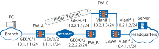
Data Plan
Item |
Data |
Description |
|
|---|---|---|---|
FW_A |
(1) |
Interface ID: GigabitEthernet 0/0/1 IP address: 10.1.1.1/24 Security zone: Trust |
- |
(2) |
Interface ID: GigabitEthernet 0/0/2 IP address: 1.1.1.1/24 Security zone: Untrust |
- |
|
IPSec configuration |
Establishment method: non-policy template Encapsulation mode: tunnel mode Security protocol: ESP ESP authentication algorithm: SHA2-256 ESP encryption algorithm: AES-256 IKE negotiation mode: main mode Pre-shared IKE key: Admin@123 IKE authentication algorithm: SHA2 NAT traversal: enabled IKE version: IKEv1 |
- |
|
FW_B |
(3) |
Interface ID: GigabitEthernet 0/0/2 IP address: 2.2.2.2/24 Security zone: Untrust |
- |
(4) |
Interface ID: GigabitEthernet 0/0/1 IP address: 10.2.1.1/24 Security zone: Trust |
- |
|
NAT server configuration |
Global IP address: 3.1.1.1 Inside IP address: 10.2.1.3 |
The inside IP address is the IP address of the VLANIF1 on the FW_C. |
|
FW_C |
(5) |
Interface ID: GigabitEthernet 0/0/1 Mode: Layer 2 VLAN ID: 10 Security zone: Untrust |
Connects to FW_B and applies IPSec policies. |
(6) |
Interface ID: GigabitEthernet 0/0/2 Mode: Layer 2 VLAN ID: 1 Security zone: Trust |
Connects to the L3SW device. |
|
VLANIF10 |
IP address: 10.2.1.3/24 Security zone: Trust |
- |
|
IPSec configuration |
Establishment method: policy template Encapsulation mode: tunnel mode Security protocol: ESP ESP authentication algorithm: SHA2-256 ESP encryption algorithm: AES-256 IKE negotiation mode: main mode Pre-shared IKE key: Admin@123 IKE authentication algorithm: SHA2 NAT traversal: enabled IKE version: IKEv1 |
- |
|
L3SW |
(7) |
Interface ID: GigabitEthernet 0/0/1 VLAN ID: 1 |
- |
(8) |
Interface ID: GigabitEthernet 0/0/2 VLAN ID: 3 |
- |
|
VLANIF110 |
IP address: 10.2.1.2/24 |
- |
|
VLANIF120 |
IP address: 10.4.1.1/24 |
The IP address of VLANIF120 is the intranet gateway. |
|
Configuration Roadmap
FW_A serves as the egress gateway of the branch and establishes IPSec tunnels with the headquarters in non-template mode.
- FW_C establishes IPSec tunnels with FW_A in template mode. IPSec policies apply on Layer-2 GigabitEthernet 0/0/1, which borrows the IP address of VLANIF1 to establish IPSec tunnels with the branch.
Procedure
- Configure FW_A.
- Configure the firewall policies.
- Configure the Trust-Untrust interzone policy to allow the unencapsulated and decapsulated packets through FW_A.
[FW_A] security-policy
[FW_A-policy-security] rule name 1
[FW_A-policy-security-rule-1] source-zone trust
[FW_A-policy-security-rule-1] destination-zone untrust
[FW_A-policy-security-rule-1] source-address 10.1.1.0 24
[FW_A-policy-security-rule-1] destination-address 10.4.1.0 24
[FW_A-policy-security-rule-1] action permit
[FW_A-policy-security-rule-1] quit
[FW_A-policy-security] rule name 2
[FW_A-policy-security-rule-2] source-zone untrust
[FW_A-policy-security-rule-2] destination-zone trust
[FW_A-policy-security-rule-2] source-address 10.4.1.0 24
[FW_A-policy-security-rule-2] destination-address 10.1.1.0 24
[FW_A-policy-security-rule-2] action permit
[FW_A-policy-security-rule-2] quit
- Configure the Local-Untrust interzone policy to allow IKE negotiation packets through FW_A.

The Local-Untrust interzone policy controls whether IKE negotiation packets can pass through the FW. This policy can use the source and destination addresses, protocol, or port as the matching condition. In this example, the source and destination addresses are used as the matching condition. To use the protocol or port as the matching condition, you need to enable ESP and port 500 for UDP (port 4500 also in NAT traversal scenarios).
[FW_A-policy-security] rule name 3
[FW_A-policy-security-rule-3] source-zone local
[FW_A-policy-security-rule-3] destination-zone untrust
[FW_A-policy-security-rule-3] source-address 1.1.1.0 24
[FW_A-policy-security-rule-3] destination-address 3.1.1.0 24
[FW_A-policy-security-rule-3] action permit
[FW_A-policy-security-rule-3] quit
[FW_A-policy-security] rule name 4
[FW_A-policy-security-rule-4] source-zone untrust
[FW_A-policy-security-rule-4] destination-zone local
[FW_A-policy-security-rule-4] source-address 3.1.1.0 24
[FW_A-policy-security-rule-4] destination-address 1.1.1.0 24
[FW_A-policy-security-rule-4] action permit
[FW_A-policy-security-rule-4] quit
[FW_A-policy-security] quit
- Configure the Trust-Untrust interzone policy to allow the unencapsulated and decapsulated packets through FW_A.
- Configure the firewall policies.
- Configure FW_B.
- Configure FW_C.
- Configure VLAN and VLANIF.
- Create VLAN 1.
<sysname> system-view
[sysname] sysname FW_C
[FW_C] vlan obscure enable
[FW_C] vlan 1
[FW_C-vlan1] quit
In Layer-2 transparent mode, the request and response packets received by the device belong to different VLANs. You must run the vlan obscure enable command to enable the function of obscure VLAN. Otherwise, traffic detection is inaccurate and services are interrupted.
Add interfaces GigabitEthernet 0/0/1 and GigabitEthernet 0/0/2 to VLAN 1.
[FW_C] interface GigabitEthernet 0/0/1
[FW_C-GigabitEthernet0/0/1] portswitch
[FW_C-GigabitEthernet0/0/1] port link-type access
[FW_C-GigabitEthernet0/0/1] quit
[FW_C] interface GigabitEthernet 0/0/2
[FW_C-GigabitEthernet0/0/2] portswitch
[FW_C-GigabitEthernet0/0/2] port link-type access
[FW_C-GigabitEthernet0/0/2] quit
Create a Vlanif interface, and set the IP address for the interface.
[FW_C] interface vlanif 1
[FW_C-Vlanif1] ip address 10.2.1.3 255.255.255.0
[FW_C-Vlanif1] quit
- Add interfaces to corresponding security zones.
[FW_C] firewall zone untrust
[FW_C-zone-untrust] add interface GigabitEthernet 0/0/1
[FW_C-zone-untrust] quit
[FW_C] firewall zone trust
[FW_C-zone-trust] add interface GigabitEthernet 0/0/2
[FW_C-zone-trust] add interface vlanif 1
[FW_C-zone-trust] quit
- Create VLAN 1.
- Configure the firewall policies.
- Configure the Trust-Untrust interzone policy to allow the unencapsulated and decapsulated packets through FW_C.
[FW_C] security-policy
[FW_C-policy-security] rule name 1
[FW_C-policy-security-rule-1] source-zone trust
[FW_C-policy-security-rule-1] destination-zone untrust
[FW_C-policy-security-rule-1] source-address 10.4.1.0 24
[FW_C-policy-security-rule-1] destination-address 10.1.1.0 24
[FW_C-policy-security-rule-1] action permit
[FW_C-policy-security-rule-1] quit
[FW_C-policy-security] rule name 2
[FW_C-policy-security-rule-2] source-zone untrust
[FW_C-policy-security-rule-2] destination-zone trust
[FW_C-policy-security-rule-2] source-address 10.1.1.0 24
[FW_C-policy-security-rule-2] destination-address 10.4.1.0 24
[FW_C-policy-security-rule-2] action permit
[FW_C-policy-security-rule-2] quit
- Configure the Local-Trust interzone policy to allow IKE negotiation packets through FW_C.
The Local-Trust interzone policy controls whether IKE negotiation packets can pass through the FW. This policy can use the source and destination addresses, protocol, or port as the matching condition. In this example, the source and destination addresses are used as the matching condition. To use the protocol or port as the matching condition, you need to enable ESP and port 500 for UDP (port 4500 also in NAT traversal scenarios).
[FW_C-policy-security] rule name 3
[FW_C-policy-security-rule-3] source-zone local
[FW_C-policy-security-rule-3] destination-zone trust
[FW_C-policy-security-rule-3] source-address 10.2.1.0 24
[FW_C-policy-security-rule-3] destination-address 1.1.1.0 24
[FW_C-policy-security-rule-3] action permit
[FW_C-policy-security-rule-3] quit
[FW_C-policy-security] rule name 4
[FW_C-policy-security-rule-4] source-zone trust
[FW_C-policy-security-rule-4] destination-zone local
[FW_C-policy-security-rule-4] source-address 1.1.1.0 24
[FW_C-policy-security-rule-4] destination-address 10.2.1.0 24
[FW_C-policy-security-rule-4] action permit
[FW_C-policy-security-rule-4] quit
[FW_C-policy-security] quit
- Configure the Trust-Untrust interzone policy to allow the unencapsulated and decapsulated packets through FW_C.
- Configure VLAN and VLANIF.
- Configure L3SW (only data for key configuration is provided, and the detailed configuration procedure is omitted).
- Create a VLAN, add interfaces to the VLAN, create the Vlanif interface, and specify an IP address for the interface according to Figure 1.
- Configure a static route. The destination IP address is 10.1.1.0/24, that is, the intranet IP address of the branch. The next hop IP address is 10.2.1.1, that is, the IP address of FW_B. Packets that are sent to the branch and encrypted by IPSec can match this route.
Configuration Verification
The branch users can successfully access the server of the headquarters.
On FW_C, run display ipsec sa brief commands. IPSec tunnels are established successfully.
<FW_C> display ipsec sa brief
Current ipsec sa num:4

Spu board slot 1, cpu 1 ipsec sa information:
Number of SAs:2
    Src address   Dst address      SPI        VPN  Protocol     Algorithm
-------------------------------------------------------------------------------
    1.1.1.1       10.2.1.3        4001819557        ESP      E:AES-256 A:SHA2-256-128
    10.2.1.3      1.1.1.1         3923280450        ESP      E:AES-256 A:SHA2-256-128
Configuration Script
Configuration scripts of FW_A.
#
 sysname FW_A
#
interface GigabitEthernet0/0/1
 undo shutdown
 ip address 10.1.1.1 255.255.255.0
#
interface GigabitEthernet0/0/2
 undo shutdown
 ip address 1.1.1.1 255.255.255.0
 ipsec policy map1
#
firewall zone trust
 set priority 85
 add interface GigabitEthernet0/0/1
#
firewall zone untrust
 set priority 5
 add interface GigabitEthernet0/0/2
#
acl number 3001
 rule 5 permit ip source 10.1.1.0 0.0.0.255 destination 10.4.1.0 0.0.0.255
#
ike proposal 1
 authentication-algorithm sha2-256
 dh group14
#
ike peer peer1
 undo version 2
 pre-shared-key %$%$||{WY}=Bx3E[HD)g}9{Yu\SJ%$%$
 ike-proposal 1
 remote-address 3.1.1.1
 remote-address authentication-address 10.2.1.3
#
ipsec proposal tran1
 esp authentication-algorithm sha2-256
 esp encryption-algorithm aes-256
#
ipsec policy map1 10 isakmp
 security acl 3001
 ike-peer peer1
 proposal tran1
#
 ip route-static 3.1.1.0 255.255.255.0 1.1.1.2
 ip route-static 10.4.1.0 255.255.255.0 1.1.1.2
#
security-policy
 rule name 1
  source-zone trust
  destination-zone untrust
  source-address 10.1.1.0 mask 255.255.255.0
  destination-address 10.4.1.0 mask 255.255.255.0
  action permit
 rule name 2
  source-zone untrust
  destination-zone trust
  source-address 10.4.1.0 mask 255.255.255.0
  destination-address 10.1.1.0 mask 255.255.255.0
  action permit
 rule name 3
  source-zone local
  destination-zone untrust
  source-address 1.1.1.0 mask 255.255.255.0
  destination-address 3.1.1.0 mask 255.255.255.0
  action permit
 rule name 4
  source-zone untrust
  destination-zone local
  source-address 3.1.1.0 mask 255.255.255.0
  destination-address 1.1.1.0 mask 255.255.255.0
  action permit
#
return
Configuration scripts of FW_B.
#
 sysname FW_B
#
interface GigabitEthernet0/0/1
 undo shutdown
 ip address 10.2.1.1 255.255.255.0
#
interface GigabitEthernet0/0/2
 undo shutdown
 ip address 2.2.2.2 255.255.255.0
#
firewall zone trust
 set priority 85
 add interface GigabitEthernet0/0/1
#
firewall zone untrust
 set priority 5
 add interface GigabitEthernet0/0/2
#
 nat server nats global 3.1.1.1 inside 10.2.1.3
#
 ip route-static 1.1.1.0 255.255.255.0 2.2.2.1
#
return
Configuration scripts of FW_C.
#
 sysname FW_C
#
 vlan obscure enable
#
interface Vlanif1
 alias VLAN1
 ip address 10.2.1.3 255.255.255.0
#
interface GigabitEthernet0/0/1
 portswitch
 undo shutdown
 port link-type access
 ipsec policy policy1
#
interface GigabitEthernet0/0/2
 portswitch
 undo shutdown
 port link-type access
#
firewall zone trust
 set priority 85
 add interface GigabitEthernet0/0/2
 add interface Vlanif1
#
firewall zone untrust
 set priority 5
 add interface GigabitEthernet0/0/1
#
acl number 3001
 rule 5 permit ip source 10.4.1.0 0.0.0.255 destination 10.1.1.0 0.0.0.255
#
ike proposal 1
 authentication-algorithm sha2-256
 dh group14
#
ike peer peer1
 undo version 2
 pre-shared-key %$%$||{WY}=Bx3E[HD)g}9{Yu\SJ%$%$
 ike-proposal 1
#
ipsec proposal p1
 esp authentication-algorithm sha2-256
 esp encryption-algorithm aes-256
#
ipsec policy-template template1 1
 acl 3001
 ike-peer peer1
 proposal p1
#
ip route-static 1.1.1.0 255.255.255.0 10.2.1.1
ip route-static 10.4.1.0 255.255.255.0 10.2.1.2
#
security-policy
 rule name 1
  source-zone trust
  destination-zone untrust
  source-address 10.4.1.0 mask 255.255.255.0
  destination-address 10.1.1.0 mask 255.255.255.0
  action permit
 rule name 2
  source-zone untrust
  destination-zone trust
  source-address 10.1.1.0 mask 255.255.255.0
  destination-address 10.4.1.0 mask 255.255.255.0
  action permit
 rule name 3
  source-zone local
  destination-zone trust
  source-address 10.2.1.0 mask 255.255.255.0
  destination-address 1.1.1.0 mask 255.255.255.0
  action permit
 rule name 4
  source-zone trust
  destination-zone local
  source-address 1.1.1.0 mask 255.255.255.0
  destination-address 10.2.1.0 mask 255.255.255.0
  action permit
#
return