CLI: Example for Establishing IPSec Tunnels Between Base Stations and the IKEv2 Redirection Group
Networking Requirements
A large number of eNodeBs need to access the LTE core network. FWs are deployed as IPSec gateways, and IPSec tunnels are established between the eNodeBs and the FWs to secure the LTE core network. When a large amount of customer traffic passes through the LTE network, three FWs are deployed to form an IPSec gateway cluster. As shown in Figure 1, FW_A and FW_B are added to a VRRP group. FW_A is the active device, and FW_B is the standby device in the VRRP group.
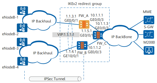
Data Plan
Item |
Data |
|---|---|
FW_A |
Interface number: GigabitEthernet 0/0/3 IP address: 10.1.1.1/24 Security zone: Trust |
Interface number: GigabitEthernet 0/0/1 IP address: 1.1.3.1/24 Security zone: Untrust The device is added to VRRP1 group and is configured as the active device. |
|
IPSec policy template configuration Remote address: not specified Authentication type: RSA-Signature Certificate: applied certificate a_local.cer IKEv2 redirection phase: Init Local ID type: IP address Peer ID type: any |
|
FW_B |
Interface number: GigabitEthernet 0/0/1 IP address: 1.1.4.1/24 Security zone: Untrust The device is added to VRRP1 group and is configured as the standby device. |
Interface number: GigabitEthernet 0/0/3 IP address: 10.1.1.2/24 Security zone: Trust |
|
IPSec policy template configuration Remote address: not specified Authentication type: RSA-Signature Certificate: applied certificate b_local.cer IKEv2 redirection phase: Init Local ID type: IP address Peer ID type: any |
|
FW_C |
Interface number: GigabitEthernet 0/0/1 IP address: 1.1.5.1/24 Security zone: Trust |
Interface number: GigabitEthernet 0/0/3 IP address: 10.1.1.3/24 Security zone: Untrust |
|
IPSec policy template configuration Remote address: not specified Authentication type: RSA-Signature Certificate: applied certificate c_local.cer IKEv2 redirection phase: Init Local ID type: IP address Peer ID type: any |
Configuration Roadmap
- Add FW_A and FW_B to a VRRP group and configure FW_A as the active device and FW_B as the standby device.
- Configure a static route and OSPF routes.
- Configure security policies.
- Configure a load balancing group for IKEv2 redirection.
- Configure IPSec.
This section provides only the configuration of FW_A, the difference between the configurations of FW_A and those of FW_B and FW_C, and configuration files.
Procedure
- Perform basic configurations on FW_A and add it to a VRRP group.

The configuration of the upstream and downstream interfaces of FW_B is same as that of FW_A except that:
- The interface IP addresses are different.
- The VRRP group status on FW_B is standby.
FW_C does not belong to any VRRP group. Therefore, you need to configure only interface IP addresses and security zones for FW_C.
Configure IP addresses for the upstream and downstream interfaces.
<sysname> system-view
[sysname] sysname FW_A
[FW_A] interface GigabitEthernet 0/0/3
[FW_A-GigabitEthernet0/0/3] ip address 10.1.1.1 24
[FW_A-GigabitEthernet0/0/3] quit
[FW_A] interface GigabitEthernet 0/0/1
[FW_A-GigabitEthernet0/0/1] ip address 1.1.3.1 24
[FW_A-GigabitEthernet0/0/1] vrrp vrid 1 virtual-ip 1.1.1.1 24 active
[FW_A-GigabitEthernet0/0/1] quit
Add interfaces to security zones.
[FW_A] firewall zone trust
[FW_A-zone-trust] add interface GigabitEthernet 0/0/3
[FW_A-zone-trust] quit
[FW_A] firewall zone untrust
[FW_A-zone-untrust] add interface GigabitEthernet 0/0/1
[FW_A-zone-untrust] quit
Configure a static route to the LTE base stations. Assume that the next hop of the static route is 1.1.1.2.
[FW_A] ip route-static 0.0.0.0 0.0.0.0 1.1.1.2
- Configure OSPF on FW_A.
The configuration of FW_B and FW_C is similar to that of FW_A.
[FW_A] ospf 1
[FW_A-ospf-1] import-route unr
[FW_A-ospf-1] area 0.0.0.0
[FW_A-ospf-1-area-0.0.0.0] network 10.1.1.0 0.0.0.255
- Configure interzone security policies on FW_A.
The configuration of FW_B and FW_C is similar to that of FW_A.
Configure the security policies between the Trust and Untrust zones.
[FW_A] security-policy
[FW_A-policy-security] rule name policy1
[FW_A-policy-security-rule-policy1] source-zone trust
[FW_A-policy-security-rule-policy1] destination-zone untrust
[FW_A-policy-security-rule-policy1] source-address 10.1.1.0 24
[FW_A-policy-security-rule-policy1] action permit
[FW_A-policy-security-rule-policy1] quit
[FW_A-policy-security] rule name policy2
[FW_A-policy-security-rule-policy2] source-zone untrust
[FW_A-policy-security-rule-policy2] destination-zone trust
[FW_A-policy-security-rule-policy2] destination-address 10.1.1.0 24
[FW_A-policy-security-rule-policy2] action permit
[FW_A-policy-security-rule-policy2] quit
Configure the security policies between the Untrust and Local zones.
The Local-Untrust interzone policy controls whether IKE negotiation packets can pass through the FW. This policy can use the source and destination addresses, protocol, or port as the matching condition. In this example, the source and destination addresses are used as the matching condition. To use the protocol or port as the matching condition, you need to enable ESP and port 500 for UDP (port 4500 also in NAT traversal scenarios).
[FW_A-policy-security] rule name policy3
[FW_A-policy-security-rule-policy3] source-zone local
[FW_A-policy-security-rule-policy3] destination-zone untrust
[FW_A-policy-security-rule-policy3] source-address 1.1.1.1 32
[FW_A-policy-security-rule-policy3] action permit
[FW_A-policy-security-rule-policy3] quit
[FW_A-policy-security] rule name policy4
[FW_A-policy-security-rule-policy4] source-zone untrust
[FW_A-policy-security-rule-policy4] destination-zone local
[FW_A-policy-security-rule-policy4] destination-address 1.1.1.1 32
[FW_A-policy-security-rule-policy4] action permit
[FW_A-policy-security-rule-policy4] quit
[FW_A-policy-security] quit
The Untrust-Local interzone policies enable successful tunnel establishment.
- Configure a load balancing group on FW_A.
The configuration of FW_B and FW_C is similar to that of FW_A. You can adjust the values of the overload-manage and member parameters as required.
[FW_A] loadgroup lte
[FW_A-loadgroup-lte] server-ip 1.1.1.1
[FW_A-loadgroup-lte] authentication-key huawei@123
[FW_A-loadgroup-lte] overload-manage limit 80 ipsec-bandwidth 100 sa-number 100
[FW_A-loadgroup-lte] member hello 5 max-ipsec-tunnel-number 64000 max-ipsec-bandwidth 4000000
- Configure an IPSec policy and apply the policy to the corresponding interface on FW_A.
The configuration of FW_B and FW_C is similar to that of FW_A.
The IKE and IPSec parameters on the FWs must be the same as those on the eNodeBs.
Verification
Check the load balancing group on FW_A.
<FW_A> display loadgroup brief
LoadGroup number: 2
 ------------------------------------------------------------------------------
 name    Server IP       Local-address   port  cookie   msgid     flag
 ------------------------------------------------------------------------------
enodeb   1.1.1.1         1.1.4.1       12013  a623c099   13af3     1
enodeb   1.1.1.1         1.1.5.1       12013  72d9999c   5522      1
Check IPSec tunnel information. In the following example, eNodeB-1 establishes an IPSec tunnel with FW_A. The IP addresses of S1 connected to the MME and S-GW are 6.1.3.1 and 6.1.2.1 respectively.
<FW_A> display ike sa

Ike sa information :
Conn-ID       Peer            VPN                 Flag(s)     Phase
  ------------------------------------------------------------------------------
67109680   6.1.3.1                               RD|M         2
67109679   6.1.3.1                               RD|M         1
67106560   6.1.2.1                               RD|M         2
67106559   6.1.2.1                               RD|M         1

  Number of SA entries  : 4

  Number of SA entries of all cpu : 4

  Flag Description:
  RD--READY   ST--STAYALIVE   RL--REPLACED   FD--FADING   TO--TIMEOUT
  HRT--HEARTBEAT   LKG--LAST KNOWN GOOD SEQ NO.   BCK--BACKED UP
  M--ACTIVE   S--STANDBY   A--ALONE  NEG--NEGOTIATING
Configuration Files
-
#
 sysname FW_A
#
acl number 3000
 rule 20 permit ip source 10.1.1.0 0.0.0.255
#
ipsec proposal tran1
 esp authentication-algorithm sha2-256
 esp encryption-algorithm aes-256
#
ike proposal 10
 encryption-algorithm aes-256
 dh group14
 authentication-algorithm sha2-256
 authentication-method rsa-signature
 integrity-algorithm hmac-sha2-256
 prf hmac-sha2-256
#
ike peer b
 ike-proposal 10
 certificate local-filename a_local.cer
 ikev2-redirect-group lte init
#
ipsec policy-template map_temp 1
 security acl 3000
 ike-peer b
 proposal tran1
 route inject dynamic
#
ipsec policy map1 20 isakmp template map_temp
#
interface GigabitEthernet0/0/3
 undo shutdown
 ip address 10.1.1.1 255.255.255.0
#
interface GigabitEthernet0/0/1
 undo shutdown
 ip address 1.1.3.1 255.255.255.0
 vrrp vrid 1 virtual-ip 1.1.1.1 255.255.255.0 active
 ipsec policy map1
#
firewall zone trust
 set priority 85
 add interface GigabitEthernet0/0/3
#
firewall zone untrust
 set priority 5
 add interface GigabitEthernet0/0/1
#
ospf 1
 import-route unr
 area 0.0.0.0
  network 10.1.1.0 0.0.0.255
#
ip route-static 0.0.0.0 0.0.0.0 1.1.1.2
#
loadgroup lte
 server-ip 1.1.1.1
 authentication-key %$%$Zq2(QRQn17(+,e-zzPH+P:gT%$%$
 overload-manage limit 80 ipsec-bandwidth 100 sa-number 100
 member hello 5 max-ipsec-tunnel-number 64000 max-ipsec-bandwidth 4000000
#
security-policy
 rule name policy1
  source-zone trust
  destination-zone untrust
  source-address 10.1.1.0 255.255.255.0
  action permit
 rule name policy2
  source-zone untrust
  destination-zone trust
  destination-address 10.1.1.0 255.255.255.0
  action permit
 rule name policy3
  source-zone local
  destination-zone untrust
  source-address 1.1.1.1 255.255.255.255
  action permit
 rule name policy4
  source-zone untrust
  destination-zone local
  destination-address 1.1.1.1 255.255.255.255
  action permit
#
return
-
#
 sysname FW_B
#
acl number 3000
 rule 20 permit ip source 10.1.1.0 0.0.0.255
#
ipsec proposal tran1
 esp authentication-algorithm sha2-256
 esp encryption-algorithm aes-256
#
ike proposal 10
 encryption-algorithm aes-256
 dh group14
 authentication-algorithm sha2-256
 authentication-method rsa-signature
 integrity-algorithm hmac-sha2-256
 prf hmac-sha2-256
#
ike peer b
 ike-proposal 10
 certificate local-filename b_local.cer
 ikev2-redirect-group lte init
#
ipsec policy-template map_temp 1
 security acl 3000
 ike-peer b
 proposal tran1
 route inject dynamic
#
ipsec policy map1 20 isakmp template map_temp
#
interface GigabitEthernet0/0/3
 undo shutdown
 ip address 10.1.1.2 255.255.255.0
#
interface GigabitEthernet0/0/1
 undo shutdown
 ip address 1.1.4.1 255.255.255.0
 vrrp vrid 1 virtual-ip 1.1.1.1 255.255.255.0 standby
 ipsec policy map1
#
firewall zone trust
 set priority 85
 add interface GigabitEthernet0/0/3
#
firewall zone untrust
 set priority 5
 add interface GigabitEthernet0/0/1
#
ospf 1
 import-route unr
 area 0.0.0.0
  network 10.1.1.0 0.0.0.255
#
ip route-static 0.0.0.0 0.0.0.0 1.1.1.2
#
loadgroup lte
 server-ip 1.1.1.1
 authentication-key %$%$Zq2(QRQn17(+,e-zzPH+P:gT%$%$
 overload-manage limit 80 ipsec-bandwidth 100 sa-number 100
 member hello 5 max-ipsec-tunnel-number 64000 max-ipsec-bandwidth 4000000
#
security-policy
 rule name policy1
  source-zone trust
  destination-zone untrust
  source-address 10.1.1.0 255.255.255.0
  action permit
 rule name policy2
  source-zone untrust
  destination-zone trust
  destination-address 10.1.1.0 255.255.255.0
  action permit
 rule name policy3
  source-zone local
  destination-zone untrust
  source-address 1.1.1.1 255.255.255.255
  action permit
 rule name policy4
  source-zone untrust
  destination-zone local
  destination-address 1.1.1.1 255.255.255.255
  action permit
#
return
-
#
 sysname FW_C
#
acl number 3000
 rule 20 permit ip source 10.1.1.0 0.0.0.255
#
ipsec proposal tran1
 esp authentication-algorithm sha2-256
 esp encryption-algorithm aes-256
#
ike proposal 10
 encryption-algorithm aes-256
 dh group14
 authentication-algorithm sha2-256
 authentication-method rsa-signature
 integrity-algorithm hmac-sha2-256
 prf hmac-sha2-256
#
ike peer b
 ike-proposal 10
 certificate local-filename c_local.cer
 ikev2-redirect-group lte init
#
ipsec policy-template map_temp 1
 security acl 3000
 ike-peer b
 proposal tran1
 route inject dynamic
#
ipsec policy map1 20 isakmp template map_temp
#
interface GigabitEthernet0/0/3
 undo shutdown
 ip address 10.1.1.3 255.255.255.0
#
interface GigabitEthernet0/0/1
 undo shutdown
 ip address 1.1.5.1 255.255.255.0
 ipsec policy map1
#
firewall zone trust
 set priority 85
 add interface GigabitEthernet0/0/3
#
firewall zone untrust
 set priority 5
 add interface GigabitEthernet0/0/1
#
ospf 1
 import-route unr
 area 0.0.0.0
  network 10.1.1.0 0.0.0.255
#
ip route-static 0.0.0.0 0.0.0.0 1.1.1.2
#
loadgroup lte
 server-ip 1.1.1.1
 authentication-key %$%$Zq2(QRQn17(+,e-zzPH+P:gT%$%$
 overload-manage limit 80 ipsec-bandwidth 100 sa-number 100
 member hello 5 max-ipsec-tunnel-number 64000 max-ipsec-bandwidth 4000000
#
security-policy
 rule name policy1
  source-zone trust
  destination-zone untrust
  source-address 10.1.1.0 255.255.255.0
  action permit
 rule name policy2
  source-zone untrust
  destination-zone trust
  destination-address 10.1.1.0 255.255.255.0
  action permit
 rule name policy3
  source-zone local
  destination-zone untrust
  source-address 1.1.1.1 255.255.255.255
  action permit
 rule name policy4
  source-zone untrust
  destination-zone local
  destination-address 1.1.1.1 255.255.255.255
  action permit
#
return