CLI: Example for Configuring BFD-OSPF Interworking
In OSPF networking with multiple devices, BFD delivers rapid fault detection.
Networking Requirements
As shown in Figure 1, FW_A carries main services of an enterprise and OSPF runs between FW_B and FW_C. The link from FW_A to FW_B is an active link, whereas the link from FW_A, FW_C, to FW_B is a standby link. It is required that traffic can be immediately switched to the standby link when the active link is faulty, and it can be also switched back after the active link is recovered.
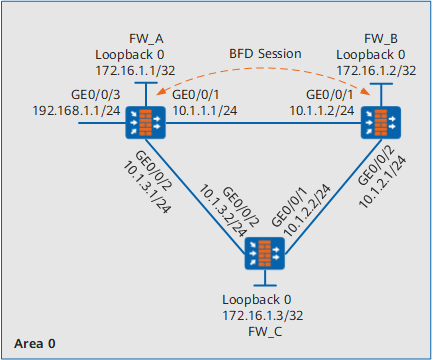
Configuration Roadmap
The configuration roadmap is as follows:
OSPF runs among FW_A, FW_B, and FW_C. The OSPF neighbor status is Full.
To monitor the active link, enable BFD for the OSPF process on each device.
To better switch traffic on the active link, enable BFD between FW_A and FW_B.
Procedure
- Configure FW_A.

This example describes only major BFD-related configurations, with IP address and security zone configurations omitted.
# Configure basic OSPF functions.
<FW_A> system-view
[FW_A] ospf 100
[FW_A-ospf-100] area 0
[FW_A-ospf-100-area-0.0.0.0] network 172.16.1.1 0.0.0.0
[FW_A-ospf-100-area-0.0.0.0] network 10.1.1.0 0.0.0.255
[FW_A-ospf-100-area-0.0.0.0] network 10.1.3.0 0.0.0.255
[FW_A-ospf-100-area-0.0.0.0] network 192.168.1.0 0.0.0.255
[FW_A-ospf-100-area-0.0.0.0] quit
[FW_A-ospf-100] quit
# Enable BFD for OSPF process 100.
[FW_A] bfd
[FW_A-bfd] quit
[FW_A] ospf 100
[FW_A-ospf-100] bfd all-interfaces enable
[FW_A-ospf-100] quit
# Enable BFD for interface GigabitEthernet 0/0/1. Set the minimum sending and receiving interval to 500 ms, and the local detection multiple to 4.
[FW_A] interface GigabitEthernet 0/0/1
[FW_A-GigabitEthernet0/0/1] ospf bfd enable
[FW_A-GigabitEthernet0/0/1] ospf bfd min-tx-interval 500 min-rx-interval 500 detect-multiplier 4
[FW_A-GigabitEthernet0/0/1] quit
# Configure security policies between the Local zone and the security zone where GE0/0/1 and GE0/0/2 resides to permit BFD packets.
[FW_A] firewall zone untrust
[FW_A-zone-untrust] add interface GigabitEthernet 0/0/1
[FW_A-zone-untrust] add interface GigabitEthernet 0/0/2
[FW_A-zone-untrust] quit
[FW_A] security-policy
[FW_A-policy-security] rule name bfd1
[FW_A-policy-security-rule-bfd1] source-zone local
[FW_A-policy-security-rule-bfd1] destination-zone untrust
[FW_A-policy-security-rule-bfd1] action permit
[FW_A-policy-security-rule-bfd1] quit
[FW_A-policy-security] rule name bfd2
[FW_A-policy-security-rule-bfd2] source-zone untrust
[FW_A-policy-security-rule-bfd2] destination-zone local
[FW_A-policy-security-rule-bfd2] action permit
[FW_A-policy-security-rule-bfd2] quit
- Configure FW_B.
# Configure basic OSPF functions.
<FW_B> system-view
[FW_B] ospf 100
[FW_B-ospf-100] area 0
[FW_B-ospf-100-area-0.0.0.0] network 172.16.1.2 0.0.0.0
[FW_B-ospf-100-area-0.0.0.0] network 10.1.1.0 0.0.0.255
[FW_B-ospf-100-area-0.0.0.0] network 10.1.2.0 0.0.0.255
[FW_B-ospf-100-area-0.0.0.0] quit
[FW_B-ospf-100] quit
# Enable BFD for OSPF process 100.
[FW_B] bfd
[FW_B-bfd] quit
[FW_B] ospf 100
[FW_B-ospf-100] bfd all-interfaces enable
[FW_B-ospf-100] quit
# Enable BFD for interface GigabitEthernet 0/0/1. Set the minimum sending and receiving interval to 500 ms, and the local detection multiple to 4.
[FW_B] interface GigabitEthernet 0/0/1
[FW_B-GigabitEthernet0/0/1] ospf bfd enable
[FW_B-GigabitEthernet0/0/1] ospf bfd min-tx-interval 500 min-rx-interval 500 detect-multiplier 4
[FW_B-GigabitEthernet0/0/1] quit
# Configure security policies between the Local zone and the security zone where GE0/0/1 and GE0/0/2 resides to permit BFD packets.
[FW_B] firewall zone trust
[FW_B-zone-trust] add interface GigabitEthernet 0/0/1
[FW_B-zone-trust] add interface GigabitEthernet 0/0/2
[FW_B-zone-trust] quit
[FW_B] security-policy
[FW_B-policy-security] rule name bfd1
[FW_B-policy-security-rule-bfd1] source-zone local
[FW_B-policy-security-rule-bfd1] destination-zone trust
[FW_B-policy-security-rule-bfd1] action permit
[FW_B-policy-security-rule-bfd1] quit
[FW_B-policy-security] rule name bfd2
[FW_B-policy-security-rule-bfd2] source-zone trust
[FW_B-policy-security-rule-bfd2] destination-zone local
[FW_B-policy-security-rule-bfd2] action permit
[FW_B-policy-security-rule-bfd2] quit
- Configure FW_C.
# Configure basic OSPF functions.
<FW_C> system-view
[FW_C] ospf 100
[FW_C-ospf-100] area 0
[FW_C-ospf-100-area-0.0.0.0] network 172.16.1.3 0.0.0.0
[FW_C-ospf-100-area-0.0.0.0] network 10.1.3.0 0.0.0.255
[FW_C-ospf-100-area-0.0.0.0] network 10.1.2.0 0.0.0.255
[FW_C-ospf-100-area-0.0.0.0] quit
[FW_C-ospf-100] quit
# Enable BFD for OSPF process 100.
[FW_C] bfd
[FW_C-bfd] quit
[FW_C] ospf 100
[FW_C-ospf-100] bfd all-interfaces enable
[FW_C-ospf-100] quit
# Configure security policies between the Local zone and the security zone where GE0/0/1 and GE0/0/2 resides to permit BFD packets.
[FW_C] firewall zone untrust
[FW_C-zone-untrust] add interface GigabitEthernet 0/0/1
[FW_C-zone-untrust] quit
[FW_C] firewall zone trust
[FW_C-zone-trust] add interface GigabitEthernet 0/0/2
[FW_C-zone-trust] quit
[FW_C] security-policy
[FW_C-policy-security] rule name bfd1
[FW_C-policy-security-rule-bfd1] source-zone local
[FW_C-policy-security-rule-bfd1] destination-zone trust untrust
[FW_C-policy-security-rule-bfd1] action permit
[FW_C-policy-security-rule-bfd1] quit
[FW_C-policy-security] rule name bfd2
[FW_C-policy-security-rule-bfd2] source-zone trust untrust
[FW_C-policy-security-rule-bfd2] destination-zone local
[FW_C-policy-security-rule-bfd2] action permit
[FW_C-policy-security-rule-bfd2] quit
Verification
After configurations are complete, view the next-hop address of the external route in the OSPF process on FW_B, to determine whether to use the active link.
# Run the display ospf routing command. You can view the next hop of 192.168.1.1 is 10.1.1.1. In this case, the active link is used.
<FW_B> display ospf routing

         OSPF Process 100 with Router ID 172.16.1.2
                  Routing Tables

 Routing for Network
 Destination        Cost  Type       NextHop         AdvRouter       Area
 10.1.3.0/24        2     Transit    10.1.1.1        172.16.1.3      0.0.0.0
 10.1.3.0/24        2     Transit    10.1.2.2        172.16.1.3      0.0.0.0
 10.1.2.0/24        1     Transit    10.1.2.1        172.16.1.3      0.0.0.0
 172.16.1.3/32         2     Stub       10.1.2.2     172.16.1.3      0.0.0.0
 172.16.1.2/32      1     Stub       172.16.1.2      172.16.1.2      0.0.0.0
 10.1.1.0/24        1     Transit    10.1.1.2        172.16.1.2      0.0.0.0
 172.16.1.1/32      2     Stub       10.1.1.1        172.16.1.1      0.0.0.0
 192.168.1.0/24     2     Stub       10.1.1.1   172.16.1.1      0.0.0.0

 Total Nets: 8
 Intra Area: 8  Inter Area: 0  ASE: 0  NSSA: 0
View the OSPF neighbor status on one device. The following uses the information displayed on FW_A as an example.
# Run the display ospf peer command to view the OSPF neighbor status. You can view that OSPF neighbor status is Full. Therefore, the BFD session is automatically established after BFD for the OSPF process is enabled.
<FW_A> display ospf peer

         OSPF Process 100 with Router ID 172.16.1.1
                 Neighbors

 Area 0.0.0.0 interface 10.1.1.1(GigabitEthernet0/0/1)'s neighbors
 Router ID: 172.16.1.2          Address: 10.1.1.2         GR State: Normal
   State: Full  Mode:Nbr is  Master  Priority: 1
   DR: 10.1.1.1  BDR: 10.1.1.2  MTU: 0
   Dead timer due in 28  sec
   Neighbor is up for 00:20:00
   Authentication Sequence: [ 0 ]

                 Neighbors

 Area 0.0.0.0 interface 10.1.3.1(GigabitEthernet0/0/2)'s neighbors
 Router ID: 172.16.1.3          Address: 10.1.3.2         GR State: Normal
   State: Full  Mode:Nbr is  Master  Priority: 1
   DR: 10.1.3.2  BDR: 10.1.3.1  MTU: 0
   Dead timer due in 38  sec
   Neighbor is up for 00:11:43
   Authentication Sequence: [ 0 ]
# Run the display ospf bfd session all command. You can view that the status of the BFD session is Up.
<FW_B> display ospf bfd session all

         OSPF Process 100 with Router ID 172.16.1.2

 NeighborId:172.16.1.1          AreaId:0.0.0.0          Interface:GigabitEthernet0/0/1
 BFDState:up                 rx    :1000             tx       :1000
 Multiplier:3                BFD Local Dis:8192      LocalIpAdd:10.1.1.2
 RemoteIpAdd:10.1.1.1        Diagnostic Info:Init

 NeighborId:172.16.1.3          AreaId:0.0.0.0          Interface:GigabitEthernet0/0/2
 BFDState:up                 rx    :1000             tx       :1000
 Multiplier:3                BFD Local Dis:8193      LocalIpAdd:10.1.2.1
 RemoteIpAdd:10.1.2.2        Diagnostic Info:Init
BFD-related parameters are modified after interface-based BFD is enabled on FW_A and FW_B.
# Run the display ospf bfd session all command to display BFD-related parameters.
<FW_A> display ospf bfd session all

         OSPF Process 100 with Router ID 172.16.1.1

 NeighborId:172.16.1.2          AreaId:0.0.0.0          Interface:GigabitEthernet0/0/1
 BFDState:up                 rx    :500              tx       :500
 Multiplier:4                BFD Local Dis:8192      LocalIpAdd:10.1.1.1
 RemoteIpAdd:10.1.1.2        Diagnostic Info:Init

 NeighborId:172.16.1.3          AreaId:0.0.0.0          Interface:GigabitEthernet0/0/2
 BFDState:up                 rx    :1000             tx       :1000
 Multiplier:3                BFD Local Dis:8193      LocalIpAdd:10.1.3.1
 RemoteIpAdd:10.1.3.2        Diagnostic Info:Init
Stimulate that the active link is faulty.
# Run the shutdown command on interface GigabitEthernet 0/0/1 of FW_A. On FW_B, you can view that the next hop of 192.168.1.1 in the OSPF routing table is route 10.1.2.2. In this case, the standby link is used.
<FW_B> display ospf routing

         OSPF Process 100 with Router ID 172.16.1.2
                  Routing Tables

 Routing for Network
 Destination        Cost  Type       NextHop         AdvRouter       Area
 10.1.3.0/24        2     Transit    10.1.2.2        172.16.1.3      0.0.0.0
 10.1.2.0/24        1     Transit    10.1.2.1        172.16.1.3      0.0.0.0
 172.16.1.3/32      2     Stub       10.1.2.2        172.16.1.3      0.0.0.0
 172.16.1.2/32      1     Stub       172.16.1.2      172.16.1.2      0.0.0.0
 172.16.1.1/32      3     Stub       10.1.2.2        172.16.1.1      0.0.0.0
 192.168.1.0/24     3     Stub       10.1.2.2   172.16.1.1      0.0.0.0

 Total Nets: 6
 Intra Area: 6  Inter Area: 0  ASE: 0  NSSA: 0
# Run the undo shutdown command on GigabitEthernet 0/0/1 of FW_A. The traffic is switched to the active link. 1 shows the routing table.
Configuration Scripts
Configuration scripts of FW_A
#
sysname FW_A
#
bfd
#
interface GigabitEthernet 0/0/1
 ip address 10.1.1.1 255.255.255.0
 ospf bfd enable
 ospf bfd min-tx-interval 500 min-rx-interval 500 detect-multiplier 4
#
interface GigabitEthernet 0/0/2
 ip address 10.1.3.1 255.255.255.0
#
interface GigabitEthernet 0/0/3
 ip address 192.168.1.1 255.255.255.0
#
interface Loopback 0
 ip address 172.16.1.1 255.255.255.255
#
ospf 100
 bfd all-interfaces enable
 area 0.0.0.0
  network 172.16.1.1 0.0.0.0
  network 10.1.1.0 0.0.0.255
  network 10.1.3.0 0.0.0.255
  network 192.168.1.0 0.0.0.255
#
security-policy
 rule name bfd1
  source-zone local
  destination-zone untrust
  action permit
 rule name bfd2
  source-zone untrust
  destination-zone local
  action permit
#
return
- Configuration scripts of FW_B
#
sysname FW_B
#
bfd
#
interface GigabitEthernet 0/0/1
 ip address 10.1.1.2 255.255.255.0
 ospf bfd enable
 ospf bfd min-tx-interval 500 min-rx-interval 500 detect-multiplier 4
#
interface GigabitEthernet 0/0/2
 ip address 10.1.2.1 255.255.255.0
#
interface Loopback 0
 ip address 172.16.1.2 255.255.255.255
#
ospf 100
 bfd all-interfaces enable
 area 0.0.0.0
  network 172.16.1.2 0.0.0.0
  network 10.1.1.0 0.0.0.255
  network 10.1.2.0 0.0.0.255
#
security-policy
 rule name bfd1
  source-zone local
  destination-zone trust
  action permit
 rule name bfd2
  source-zone trust
  destination-zone local
  action permit
#
return
Configuration scripts of FW_C
#
sysname FW_C
#
bfd
#
interface GigabitEthernet0/0/1
 ip address 10.1.2.2 255.255.255.0
 #
interface GigabitEthernet0/0/2
 ip address 10.1.3.2 255.255.255.0
#
interface Loopback 0
 ip address 172.16.1.3 255.255.255.255
#
ospf 100
 bfd all-interfaces enable
 area 0.0.0.0
  network 172.16.1.3 0.0.0.0
  network 10.1.2.0 0.0.0.255
  network 10.1.3.0 0.0.0.255
#
security-policy
 rule name bfd1
  source-zone local
  destination-zone trust
  destination-zone untrust
  action permit
 rule name bfd2
  source-zone trust
  source-zone untrust
  destination-zone local
  action permit
#
return