CLI: Example for Configuring BFD-PBR Interworking
By binding the specified PBR to the BFD session, you can adjust the PBR dynamically according to the network status.
Networking Requirements
As shown in Figure 1, an enterprise has departments A and B. Departments A and B, acting as service departments, generate heavy traffic and require different links for traffic balancing. In addition, the departments require high stability and service continuity.
To meet their requirements, the enterprise has two links (ISP1 and ISP2) to access the Internet. The two links share the traffic and can back up for each other to ensure service continuity.
The requirements are as follows:
- Department A resides on network segment 10.1.0.0/16 and its packets pass through link ISP1 in normal cases.
- Department B resides on network segment 10.2.0.0/16 and its packets pass through link ISP2 in normal cases.
- The links of departments A and B are mutually backed up. When the link (active link) of a department is faulty, traffic is switched to the link (standby link) of another department.
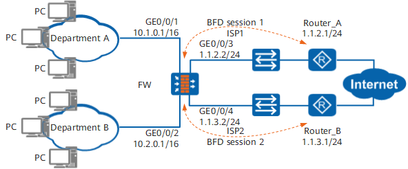
Configuration Roadmap

This example describes only PBR-related configurations, but not configurations (such as NAT and route reachability among Router_A, Router_B, and FW) required by the FW for providing Internet access.
The configuration roadmap is as follows:
To balance traffic on different links, configure the PBR based on source IP addresses, so that packets from department A pass through ISP1 and those from department B pass through ISP2.
- To ensure the continuity and mutual backup of links at which departments A and B reside, perform the following:
- Configure static BFD sessions respectively on the FW, Router_A, and Router_B to detect the link connectivity between the FW and Router_A, and between the FW and Router_B.
- Configure interworking between PBR and BFD. BFD monitors the availability of the active links of departments A and B. When the active links are faulty, PBR becomes invalid. The device searches for standby routes to ensure service continuity.
- Configure static routes from department A to link ISP2 and from department B to link ISP1 as the backup routes of departments A and B. Moreover, configure static routes to interwork with BFD. BFD monitors the availability of the standby links of departments A and B.
Procedure
- Configure the FW.
This example describes only major BFD-related configurations, with IP address and security zone configurations omitted.
- Create BFD session 1 on Router_A.
# Configure BFD session 1 with peer IP address 1.1.2.2, local discriminator 20, and remote discriminator 10.
<Router_A> system-view
[Router_A] bfd
[Router_A-bfd] quit
[Router_A] bfd 1 bind peer-ip 1.1.2.2
[Router_A-bfd-session-1] discriminator local 20
[Router_A-bfd-session-1] discriminator remote 10
[Router_A-bfd-session-1] commit
[Router_A-bfd-session-1] quit
- Create BFD session 2 on Router_B.
# Configure BFD session 2 with peer IP address 1.1.3.2, local discriminator 40, and remote discriminator 30.
<Router_B> system-view
[Router_B] bfd
[Router_B-bfd] quit
[Router_B] bfd 2 bind peer-ip 1.1.3.2
[Router_B-bfd-session-1] discriminator local 40
[Router_B-bfd-session-1] discriminator remote 30
[Router_B-bfd-session-1] commit
[Router_B-bfd-session-1] quit
Verification
When active links are reachable, packets from department A are forwarded by the FW to ISP1, and those from department B are forwarded by the FW to ISP2.
# Run the display bfd session all command. You can view that BFD sessions are created and they are in Up state.
[FW] display bfd session all
--------------------------------------------------------------------------------
Local  Remote  Peer IP Address Interface Name                  State     Type
--------------------------------------------------------------------------------
10     20      1.1.2.1         --                              Up        Static
30     40      1.1.3.1         --                              Up        Static
--------------------------------------------------------------------------------
# Run the ping 1.1.2.1 command in department A. The ping succeeds. Then run the ping 1.1.3.1 command. The ping fails.
C:\Documents and Settings\DepartA>ping 1.1.2.1

Pinging 1.1.2.1 with 32 bytes of data:

Reply from 1.1.2.1: bytes=32 time=9ms TTL=254
Reply from 1.1.2.1: bytes=32 time=2ms TTL=254
Reply from 1.1.2.1: bytes=32 time=2ms TTL=254
Reply from 1.1.2.1: bytes=32 time=5ms TTL=254

Ping statistics for 1.1.2.1:
    Packets: Sent = 4, Received = 4, Lost = 0 (0% loss),
Approximate round trip times in milli-seconds:
    Minimum = 2ms, Maximum = 9ms, Average = 4ms

C:\Documents and Settings\DepartA>ping 1.1.3.1

Pinging 1.1.3.1 with 32 bytes of data:

Request timed out.
Request timed out.
Request timed out.
Request timed out.

Ping statistics for 1.1.3.1:
    Packets: Sent = 4, Received = 0, Lost = 4 (100% loss),
# Run the ping 1.1.3.1 command in department B. The ping succeeds. Then run the ping 1.1.2.1 command. The ping fails.
C:\Documents and Settings\DepartB>ping 1.1.3.1

Pinging 1.1.3.1 with 32 bytes of data:

Reply from 1.1.3.1: bytes=32 time=2ms TTL=254
Reply from 1.1.3.1: bytes=32 time=1ms TTL=254
Reply from 1.1.3.1: bytes=32 time=1ms TTL=254
Reply from 1.1.3.1: bytes=32 time=2ms TTL=254

Ping statistics for 1.1.3.1:
    Packets: Sent = 4, Received = 4, Lost = 0 (0% loss),
Approximate round trip times in milli-seconds:
    Minimum = 1ms, Maximum = 2ms, Average = 1ms

C:\Documents and Settings\DepartB>ping 1.1.2.1

Pinging 1.1.2.1 with 32 bytes of data:

Request timed out.
Request timed out.
Request timed out.
Request timed out.

Ping statistics for 1.1.2.1:
    Packets: Sent = 4, Received = 0, Lost = 4 (100% loss),
When the active link is faulty, the FW searches for the standby route and forwards the packets of departments to the corresponding standby link. The following uses active link ISP1 of department A as an example.
# Run the display bfd session all command. The status of BFD session 1 of the link where department A resides is Down.
[FW] display bfd session all
--------------------------------------------------------------------------------
Local  Remote  Peer IP Address Interface Name                  State     Type
--------------------------------------------------------------------------------
10     20      1.1.2.1         --                              Down      Static
30     40      1.1.3.1         --                              Up        Static
--------------------------------------------------------------------------------
# Run the ping 1.1.2.1 command in department A. The ping fails. Then run the ping 1.1.3.1 command. The ping succeeds.
C:\Documents and Settings\DepartA>ping 1.1.3.1

Pinging 1.1.3.1 with 32 bytes of data:

Reply from 1.1.3.1: bytes=32 time=2ms TTL=254
Reply from 1.1.3.1: bytes=32 time=1ms TTL=254
Reply from 1.1.3.1: bytes=32 time=1ms TTL=254
Reply from 1.1.3.1: bytes=32 time=2ms TTL=254

Ping statistics for 1.1.3.1:
    Packets: Sent = 4, Received = 4, Lost = 0 (0% loss),
Approximate round trip times in milli-seconds:
    Minimum = 1ms, Maximum = 2ms, Average = 1ms

C:\Documents and Settings\DepartA>ping 1.1.2.1

Pinging 1.1.2.1 with 32 bytes of data:

Request timed out.
Request timed out.
Request timed out.
Request timed out.

Ping statistics for 1.1.2.1:
    Packets: Sent = 4, Received = 0, Lost = 4 (100% loss),
When active links restore to normal, the FW forwards all packets to the active links. The following uses active link ISP1 of department A as an example.
# Run the display bfd session all command. The status of the BFD session of the link where department A resides is Up.
[FW] display bfd session all
--------------------------------------------------------------------------------
Local  Remote  Peer IP Address Interface Name                  State     Type
--------------------------------------------------------------------------------
10     20      1.1.2.1         --                              Up        Static
30     40      1.1.3.1         --                              Up        Static
--------------------------------------------------------------------------------
# Run the ping 1.1.2.1 command in department A. The ping succeeds. Then run the ping 1.1.3.1 command. The ping fails.
C:\Documents and Settings\DepartA>ping 1.1.2.1

Pinging 1.1.2.1 with 32 bytes of data:

Reply from 1.1.2.1: bytes=32 time=2ms TTL=254
Reply from 1.1.2.1: bytes=32 time=1ms TTL=254
Reply from 1.1.2.1: bytes=32 time=1ms TTL=254
Reply from 1.1.2.1: bytes=32 time=2ms TTL=254

Ping statistics for 1.1.2.1:
    Packets: Sent = 4, Received = 4, Lost = 0 (0% loss),
Approximate round trip times in milli-seconds:
    Minimum = 1ms, Maximum = 2ms, Average = 1ms

C:\Documents and Settings\DepartA>ping 1.1.3.1

Pinging 1.1.3.1 with 32 bytes of data:

Request timed out.
Request timed out.
Request timed out.
Request timed out.

Ping statistics for 1.1.3.1:
    Packets: Sent = 4, Received = 0, Lost = 4 (100% loss),
Departments A and B can communicate with each other. In the following example, the user in department A pings that in department B.
C:\Documents and Settings\DepartA>ping 10.2.0.111

Pinging 10.2.0.111 with 32 bytes of data:

Reply from 10.2.0.111: bytes=32 time=2ms TTL=127
Reply from 10.2.0.111: bytes=32 time=1ms TTL=127
Reply from 10.2.0.111: bytes=32 time=1ms TTL=127
Reply from 10.2.0.111: bytes=32 time=2ms TTL=127

Ping statistics for 10.2.0.111:
    Packets: Sent = 4, Received = 4, Lost = 0 (0% loss),
Approximate round trip times in milli-seconds:
    Minimum = 1ms, Maximum = 2ms, Average = 1ms
Configuration Scripts
Configuration scripts of FW
#
sysname FW
#
bfd
#
interface GigabitEthernet0/0/1
 ip address 10.1.0.1 255.255.0.0
#
interface GigabitEthernet0/0/2
 ip address 10.2.0.1 255.255.0.0
#
interface GigabitEthernet0/0/3
 ip address 1.1.2.2 255.255.255.0
#
interface GigabitEthernet0/0/4
 ip address 1.1.3.2 255.255.255.0
#
bfd 1 bind peer-ip 1.1.2.1
 discriminator local 10
 discriminator remote 20
 commit
#
bfd 2 bind peer-ip 1.1.3.1
 discriminator local 30
 discriminator remote 40
 commit
#
 ip route-static 0.0.0.0 0.0.0.0 1.1.2.1 track bfd-session 1
 ip route-static 0.0.0.0 0.0.0.0 1.1.3.1 track bfd-session 2
#
policy-based-route
 rule name A_1
  ingress-interface GigabitEthernet0/0/1
  source-address 10.1.0.0 16
  destination-address 10.2.0.0 16
  action no-pbr
 rule name A_2
  ingress-interface GigabitEthernet0/0/1
  source-address 10.1.0.0 16
  track bfd-session 10
  action pbr next-hop 1.1.2.1
 rule name B_1
  ingress-interface GigabitEthernet0/0/2
  source-address 10.2.0.0 16
  destination-address 10.1.0.0 16
  action no-pbr
 rule name B_2
  ingress-interface GigabitEthernet0/0/2
  source-address 10.2.0.0 16
  track bfd-session 30
  action pbr next-hop 1.1.3.1
#
security-policy
 rule name bfd1
  source-zone local
  destination-zone untrust
  source-address 1.1.2.2 32
  source-address 1.1.3.2 32
  destination-address 1.1.2.1 32
  destination-address 1.1.3.1 32
  action permit
 rule name bfd2
  source-zone untrust
  destination-zone local
  source-address 1.1.2.1 32
  source-address 1.1.3.1 32
  destination-address 1.1.2.2 32
  destination-address 1.1.3.2 32
  action permit
#
return
Configuration scripts of Router_A
#
sysname Router_A
#
bfd
#
bfd 1 bind peer-ip 1.1.2.2
 discriminator local 20
 discriminator remote 10
 commit
#
return
Configuration scripts of Router_B
#
sysname Router_B
#
bfd
#
bfd 2 bind peer-ip 1.1.3.2
 discriminator local 40
 discriminator remote 30
 commit
#
return