Configuring an ISATAP Tunnel
ISATAP tunnels are used by IPv4/IPv6 hosts on an IPv4 network to access resources on an IPv6 network. ISATAP tunnels can be established between ISATAP hosts and border devices.
Prerequisites

ISATAP tunnels need to be configured on hosts. The configurations on hosts, however, vary according to their operating systems. For configuration details, refer to the Help information of the operating systems on hosts. In this manual, hosts with the Microsoft Windows XP Professional operating system are used as examples.
- IPv6 packet forwarding is enabled globally.
- An IPv4 address is configured for the interface connecting to an IPv4 network, the interface is Up, and the IPv4 address is routable.
Context
ISATAP tunnels apply to IPv6 networks. Therefore, ISATAP hosts use IPv6 ND to obtain ISATAP prefixes configured on ISATAP border devices.
Application Scenario
ISATAP tunnels are established between ISATAP hosts and border devices.
As shown in Figure 1, both the ISATAP router and host support the IPv6/IPv4 dual stack and connect to the IPv6 and IPv4 networks. The ISATAP tunnel connects the ISATAP host and border device, which enables PC1 and PC2 to communicate.
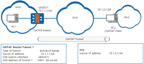
Tunnel Route
After you configure an ISATAP tunnel, ensure that the ISATAP host has a route to the ISATAP edge device to implement normal packet forwarding.
Routes from sources to destinations vary according to the operating systems of hosts.
Procedure
- Access the system view.
- Create a tunnel interface and access the tunnel interface view.
interface tunnel interface-number
- Set the tunnel encapsulation mode to ISATAP.
tunnel-protocol ipv6-ipv4 isatap
- Set a source address or interface for the ISATAP tunnel.
source { ipv4-address | interface-type interface-number }
You can set the source address of an ISATAP tunnel to the IPv4 address of the interface connecting to the IPv4 network or configure this interface as the source interface.
Moreover, you can specify a physical or logical interface, such as a loopback interface as the source interface.
Because the destination address of an ISATAP tunnel is calculated based on the source address of the peer end, the source address or source interface of the ISATAP tunnel must be unique.
- Enable the IPv6 function on the tunnel interface.
- Set an ISATAP address prefix for the tunnel interface.
ipv6 address { ipv6-address prefix-length | ipv6-address/prefix-length } eui-64
The ISATAP address prefix is the EUI-64 global unicast address configured on the border device.
Set the ISATAP address prefix to the first 64 bits of the tunnel interface address. The last 64 bits are in 5EFE: ipv4-address format. 5EFE is assigned by the Internet Assigned Numbers Authority (IANA) and ipv4-address is the source address.
The ISATAP addresses that form on the ISATAP border device and host are different. For example, the source address on the ISATAP edge device is 10.1.1.1, and the source address on the ISATAP host is 10.1.2.1. The ISATAP address prefix is 3001::/64. The generated ISATAP addresses are as follows:
- ISATAP border device: 3001::5EFE:A01:101
- ISATAP host: 3001::5EFE:10.1.2.1
- Enable the tunnel interface o advertise router advertisement (RA) messages.
The ISATAP border device uses RA messages to advertise the ISATAP address prefix to neighboring ISATAP hosts. Therefore, you need to enable the RA message advertisement function.
Example
FW_A is the border device between the IPv6 and IPv4 networks. The IPv4 address of GE0/0/1 (on the FW_A) that connects to the IPv4 network is 10.1.1.1/24. The IPv4 address of the PC is 10.1.2.1/24. An ISATAP tunnel is established between FW_A and the PC.
# On FW_A, configure a tunnel encapsulation mode, a source address, and an ISATAP address prefix for the tunnel interface.
<FW> system-view
[FW] sysname FW_A
[FW_A] ipv6
[FW_A] interface tunnel 1
[FW_A-Tunnel1] tunnel-protocol ipv6-ipv4 isatap
[FW_A-Tunnel1] ipv6 enable
[FW_A-Tunnel1] source 10.1.1.1
[FW_A-Tunnel1] ipv6 address 3001:: 64 eui-64
[FW_A-Tunnel1] undo ipv6 nd ra halt
Assume that the operating system of the PC is Microsoft Windows 2007l. IPv4 address 10.1.2.1/24 is specified for the PC. Configure IPv6 to enable the PC to obtain ISATAP address prefix 3001::/64 sent by FW_A.