Configuring a 6RD Tunnel
6RD tunnels are point-to-multipoint tunnels that connect carriers' IPv4 networks to IPv6 domains. They are widely applied to carriers' networks.
Prerequisites
Before you configure a 6RD tunnel, ensure that dual stack is enabled on the devices at both ends, and the following configurations are complete:
- IPv6 packet forwarding is enabled globally.
- The IPv4 address of the interface connecting to the IPv4 network is specified, the interface is Up, and the IPv4 address is routable.
Context
6RD tunnels build on 6to4 tunnels. The key difference in between is that 6RD tunnels use the carrier's IPv6 address prefix rather than the well-known prefix (2002::/16).
Application Scenario
6RD tunnels apply to the following scenarios:
6RD domain to 6RD domain
When 6RD domains are connected and devices at both ends of the tunnel are 6RD CE routers or 6RD BRs, hosts or devices in different domains can access each other.
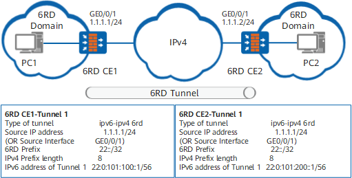
As shown in Figure 1, dual stack is enabled on 6RD CE1 and 6RD CE2, and both devices are connected to the IPv6 network and IPv4 network. The 6RD tunnel connects two 6RD domains and enables PCs or devices in different 6RD domains to communicate.
- Calculate the 6RD delegated prefix by the 6RD prefix and IPv4 prefix length. Query the 6RD delegated prefix by running the display interface Tunnel command in the Tunnel 1 interface view. The 6RD delegated prefix calculated by 6RD CE1 Tunnel 1 is 22:0:101:100::/56, and that calculated by 6RD CE2 Tunnel 1 is 22:0:101:200::/56.
- The IPv6 address prefix of the tunnel interface is the 6RD delegated prefix.
6RD domain to IPv6 network
When a 6RD domain is connected to a common IPv6 network, the 6RD CE device and 6RD BR reside on the two ends of the tunnel to ensure the communication between the 6RD domain and the IPv6 network.
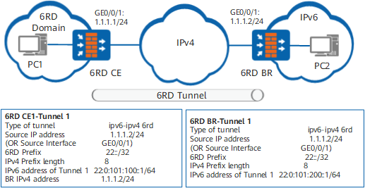
As shown in Figure 2, dual stack is enabled on the 6RD CE device and 6RD BR, and both devices are connected to the IPv6 network and IPv4 network. The 6RD tunnel connects the 6RD domain and IPv6 network and ensures the communications between PCs or devices in the 6RD domain and on the IPv6 network.
Tunnel Route
After the tunnel is established, the source and destination must have routes to each other to ensure normal packet forwarding. You can configure either static routes or dynamic routes.
To configure a static route, set the destination address to the IPv6 address of the interface on the peer IPv6 network and the outbound interface to the local tunnel interface. Note that in the 6RD domain-IPv6 network scenario, to ensure the communication between the 6RD domain and the common IPv6 network, you need to add static routes destined for the 6RD BR on the 6RD CE device.
To configure a dynamic route, enable dynamic routing protocols on the tunnel interface and the interfaces on the link that connects the IPv4 network and IPv6 network. The 6RD tunnel supports BGP4+.
Procedure
- Access the system view.
- Create a tunnel interface and access the tunnel interface view.
interface tunnel interface-number
- Set the tunnel encapsulation mode to 6RD.
tunnel-protocol ipv6-ipv4 6rd
- Specify a source IPv4 address or source interface for the 6RD tunnel.
source { ipv4-address | interface-type interface-number }
- Specify the 6RD prefix and prefix length.
ipv6-prefix ipv6-prefix/ipv6-prefix-length
The 6RD prefix, also called the IPv6 address prefix of the carrier, is the IPv6 prefix applied to the 6RD domain. Configure the same 6RD prefix within one 6RD domain.
- Specify the IPv4 mask length of the 6RD tunnel.
ipv4-prefix length prefix-length
The IPv4 mask length indicates that the high-order bits of prefix-length are deleted from the source IPv4 address of the tunnel and other bits form a part of the 6RD prefix. The 6RD delegated prefix can be calculated by combining the 6RD prefix and the IPv4 mask length.
If the IPv4 network is a carrier network, you are advised to set prefix-length to 0. In this case, the source address of the tunnel is entirely embedded in the 6RD delegated prefix and is used to search for the destination address of the tunnel.
Configure the same IPv4 prefix length of the 6RD tunnel for each 6RD domain.
After you configure the 6RD prefix, prefix length, and IPv4 prefix length, the 6RD delegated prefix can be calculated automatically. In the tunnel interface view, you can run the display interface Tunnel command to calculate the 6RD delegated prefix.
- Enable IPv6 on the tunnel interface.
- Specify an IPv6 address for the tunnel interface and use the 6RD delegated prefix as the address prefix.
ipv6 address { ipv6-address prefix-length | ipv6-address/prefix-length }
- Optional: Specify an IPv4 address for the 6RD BR.
border-relay address ipv4-address
In the 6RD domain-IPv6 network scenario, the IPv4 address of the 6RD BR needs to be specified on the 6RD CE device. As shown in Figure 2, the IPv4 address of the 6RD BR is set to 1.1.1.2/24 on the 6RD CE device. This IPv4 address is the source address of the 6RD BR.
Example
The 6RD relay scenario is used as an example for explanation.
As shown in Figure 2, FW is the CE device in the 6RD domain, and the IPv4 address of interface GigabitEthernet 0/0/1 connected to the IPv4 network is 1.1.1.1/24. FW is the BR device in the 6RD domain, and the IPv4 address of interface GigabitEthernet 0/0/1 connected to the IPv4 network is 1.1.2.1/24. Establish a 6RD tunnel between CE and BR.
# Set the 6RD tunnel type, source address, 6RD prefix, and IPv4 prefix length of CE and the IPv4 address of the 6RD BR.
<FW> system-view
[FW] sysname FW_A
[FW_A] ipv6
[FW_A] interface tunnel 1
[FW_A-Tunnel1] tunnel-protocol ipv6-ipv4 6rd
[FW_A-Tunnel1] ipv6 enable
[FW_A-Tunnel1] source 1.1.1.1
[FW_A-Tunnel1] ipv6-prefix 22::/32
[FW_A-Tunnel1] ipv4-prefix length 8
[FW_A-Tunnel1] border-relay address 1.1.1.2
# Display the calculated 6RD delegated prefix.
[FW_A] display interface Tunnel 1
Tunnel1 current state : UP
Line protocol current state : UP
Description:Tunnel1 Interface
Route Port,The Maximum Transmit Unit is 1500
Internet protocol processing : disabled
Encapsulation is TUNNEL, loopback not set
Tunnel source 1.1.1.1(GigabitEthernet 0/0/1), destination auto
Tunnel protocol/transport IPV6 over IPv4(6rd)
ipv6 prefix 22::/32
ipv4 prefix length 8
6RD Operational, Delegated Prefix is 22:0:101:100::/56
# Set the IPv6 address of the tunnel interface based on the 6RD delegated prefix, tunnel source address, and IPv4 prefix length.
[FW_A-Tunnel1] ipv6 address 22:0:101:100::1 56
# Configure routes to the IPv6 network connected to FW. (IPv6 address of the Tunnel is 3001::1/64.)
[FW_A] ipv6 route-static 22:: 32 Tunnel 1
[FW_A] ipv6 route-static 3001:: 64 22:0:101:200::1
# Set the 6RD tunnel type, source address, 6RD prefix, and IPv4 prefix length of FW.
<FW> system-view
[FW] sysname FW_B
[FW_B] ipv6
[FW_B] interface tunnel 1
[FW_B-Tunnel1] tunnel-protocol ipv6-ipv4 6rd
[FW_B-Tunnel1] ipv6 enable
[FW_B-Tunnel1] source 1.1.1.2
[FW_B-Tunnel1] ipv6-prefix 22::/32
[FW_B-Tunnel1] ipv4-prefix length 8
# Display the calculated 6RD delegated prefix.
[FW_B] display interface Tunnel 1
Tunnel1 current state : UP
Line protocol current state : UP
Description:Tunnel1 Interface
Route Port,The Maximum Transmit Unit is 1500
Internet protocol processing : disabled
Encapsulation is TUNNEL, loopback not set
Tunnel source 1.1.1.2(GigabitEthernet 0/0/1), destination auto
Tunnel protocol/transport IPV6 over IPv4(6rd)
ipv6 prefix 22::/32
ipv4 prefix length 8
6RD Operational, Delegated Prefix is 22:0:101:200::/56
# Set an IPv6 address for the tunnel interface based on the 6RD delegated prefix, tunnel source address, and IPv4 prefix length.
[FW_B-Tunnel1] ipv6 address 22:0:101:200::1 56
# Configure a route to the IPv6 network connected to FW_B.
[FW_B] ipv6 route-static 22:: 32 tunnel 1
Follow-up Procedure
After the configuration is complete, run the display ipv6 interface tunnel command in any view to check the IPv6 status and configuration of Tunnel 1. FW_A is used as an example for explanation.
[FW_A] display ipv6 interface tunnel 1
Tunnel1 current state : UP
IPv6 protocol current state : UP
IPv6 is enabled, link-local address is FE80::101:101
  Global unicast address(es):
    22:0:101:100::1, subnet is 22:0:101:100::/64
  Joined group address(es):
    FF02::1:FF00:1
    FF02::1:FF01:101
    FF02::2
    FF02::1
  MTU is 1480 bytes
  Encapsulation is TUNNEL, loopback not set
  Tunnel source: 1.1.1.1 (GigabitEthernet0/0/1), destination: unknown
  Tunnel protocol/transport: IPv6 over IPv4(6rd)/IP
  6RD tunnel IPv6 prefix: 22::, IPv6 prefix length: 32
  6RD tunnel IPv4 prefix length: 8
  6RD tunnel delegation prefix: 22:0:101:200::, delegation prefix length: 56
  6RD tunnel border relay: 1.1.1.2