CLI: Example for Configuring VLAN Interfaces to Allow VLANs to Communicate
In the networking, users belong to different VLANs. To implement the communication between devices in different VLANs, you can assign IP addresses to VLANIF interfaces.
Networking Requirements
As shown in Figure 1, two project teams in the same R&D department which need to be isolated belong to different VLANs. To enable project teams to coordinate with each other, ensure that PCs in these project teams can communicate.
VLAN2 and VLAN3 can communicate through VLANIF interfaces.
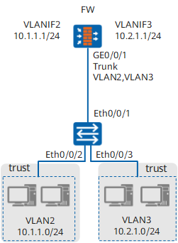
Configuration Roadmap
The configuration roadmap is as follows:
- Configure VLANs and add Layer-2 Ethernet interfaces.
- Configure Vlanif interfaces.
- Add the interfaces to security zones and configure security policies.
- Configure the host gateway.

The default gateway address of each PC in a VLAN must be the IP address of the corresponding VLANIF interface. Otherwise, inter-VLAN communication will fail.
Procedure
- Configure VLANs and add interfaces.
# Create VLAN2.
<FW> system-view
[FW] vlan 2
[FW-vlan-2] quit
# Create VLAN3.
<FW> system-view
[FW] vlan 3
[FW-vlan-3] quit
# Configure the GigabitEthernet 0/0/1 interface.
[FW] interface GigabitEthernet 0/0/1
[FW-GigabitEthernet 0/0/1] portswitch
[FW-GigabitEthernet 0/0/1] port link-type trunk
[FW-GigabitEthernet 0/0/1] port trunk allow-pass vlan 2 3
[FW-GigabitEthernet 0/0/1] undo port trunk allow-pass vlan 1
[FW-GigabitEthernet 0/0/1] quit
- Configure Vlanif interfaces.
# Set the IP address of Vlanif 2.
[FW] interface Vlanif 2
[FW-Vlanif2]ip address 10.1.1.1 24
[FW-Vlanif2]quit
# Set the IP address of Vlanif 3.
[FW] interface Vlanif 3
[FW-Vlanif3]ip address 10.2.1.1 24
[FW-Vlanif3]quit
- Add the VLANIF interfaces into a security zone and configure a security policy.
[FW]firewall zone trust
[FW-trust]add interface Vlanif2
[FW-trust]add interface Vlanif3
[FW-trust]quit
[FW]security-policy
[FW-security-policy]rule name sec_policy_1
[FW-security-policy-sec_policy_1]source-zone trust
[FW-security-policy-sec_policy_1]destination-zone trust
[FW-security-policy-sec_policy_1]action permit
- Configure the switch.
The following configuration uses the Quidway S2300 is as the switch. In actual practice, refer to the documents of the switch you use.
# Create VLAN2 and VLAN3, and add Ethernet 0/0/2 to VLAN2 and Ethernet 0/0/3 to VLAN3.
[Switch] vlan batch 2 3
[Switch] interface ethernet 0/0/2
[Switch-Ethernet0/0/2] port link-type access
[Switch-Ethernet0/0/2] port default vlan 2
[Switch-Ethernet0/0/2] quit
[Switch] interface ethernet 0/0/3
[Switch-Ethernet0/0/3] port link-type access
[Switch-Ethernet0/0/3] port default vlan 3
[Switch-Ethernet0/0/3] quit
# Configure the Layer-2 interface Ethernet 0/0/1 as a VLAN trunk interface and permit the packets from VLAN2 and VLAN3 to pass through Ethernet 0/0/1.
[Switch] interface Ethernet 0/0/1
[Switch-Ethernet0/0/1] port link-type trunk
[Switch-Ethernet0/0/1] port trunk allow-pass vlan 2 3
[Switch-Ethernet0/0/1] undo port trunk allow-pass vlan 1
[Switch-Ethernet0/0/1] quit
- Set the IP address of the host gateway that belongs to VLAN2 to 10.1.1.1 and set that belongs to VLAN3 to 10.2.1.1.
After the configuration, the hosts in VLAN2 and VLAN3 can ping through each other. Suppose that a host at IP address 10.2.1.5 exists on VLAN3, and you run the ping command on a certain host on VLAN2 to test the communications with the host on VLAN3.
C:\Documents and Settings\Administrator> ping 10.2.1.5

Pinging 10.2.1.5 with 32 bytes of data:
Reply from 10.2.1.5: bytes=32 time=1ms TTL=255
Reply from 10.2.1.5: bytes=32 time=2ms TTL=255
Reply from 10.2.1.5: bytes=32 time=1ms TTL=255
Reply from 10.2.1.5: bytes=32 time=1ms TTL=255

Ping statistics for 10.2.1.5:
    Packets: Sent = 4, Received = 4, Lost = 0 (0% loss),
Approximate round trip times in milli-seconds:
    Minimum = 1ms, Maximum = 2ms, Average = 1ms
Configuration Scripts
#
 vlan batch 2 to 3
#
interface Vlanif2
 ip address 10.1.1.1 255.255.255.0
#
interface Vlanif3
 ip address 10.2.1.1 255.255.255.0
#
interface GigabitEthernet 0/0/1
 portswitch
 undo shutdown
 port link-type trunk
 port trunk allow-pass vlan 2 3
#
firewall zone trust
 set priority 85
 add interface GigabitEthernet 0/0/1
 add interface Vlanif2
 add interface Vlanif3
#
security-policy
  rule name sec_policy_1
    source-zone trust
    destination-zone trust
    action permit
#
return