Web: Example for Configuring Basic OSPF Functions
You can divide OSPF backbone and non-backbone areas to reduce the number of LSAs on the network and enhance the scalability of OSPF networks.
Networking Requirements

This configuration example covers only OSPF-related configuration commands.
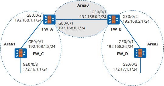
As shown in Figure 1, all the FWs run OSPF, and the whole Autonomous System (AS) is divided into three areas. The FW_A and FW_B serve as ABRs to forward the routes between these areas.
After the configuration, each FWcan learn the routes from AS to all network segments.
Configuration Roadmap
The configuration roadmap is as follows:
- Enabling OSPF on each FWand specifying the network segment in different area
- Checking the routing list and database information
Data Preparation
To complete the configuration, you need the following data:
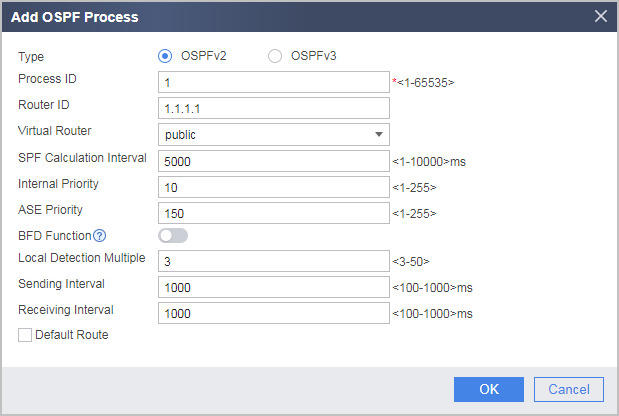
- The router ID of the FW_A is 1.1.1.1. the OSPF process number is 1. Network segment 192.168.0.0 is specified in Area 0, and network segment 192.168.1.0 is specified in Area 1.
- The router ID of the FW_B is 2.2.2.2. the OSPF process number is 1. Network segment 192.168.0.0 is specified in Area 0, and network segment 192.168.2.0 is specified in Area 2.
- The router ID of the FW_C is 3.3.3.3. the OSPF process number is 1. Network segment 192.168.1.0 and 172.16.1.0 are specified in Area 1.
- The router ID of the FW_D is 4.4.4.4. the OSPF process number is 1. Network segment 192.168.2.0 and 172.17.1.0. are specified in Area 2.
Procedure
- Set the IP address of FW_A, assign the
interface to a security zone, and configure an interzone security
policy.
- Configure basic OSPF functions of FW_A.
- Choose .
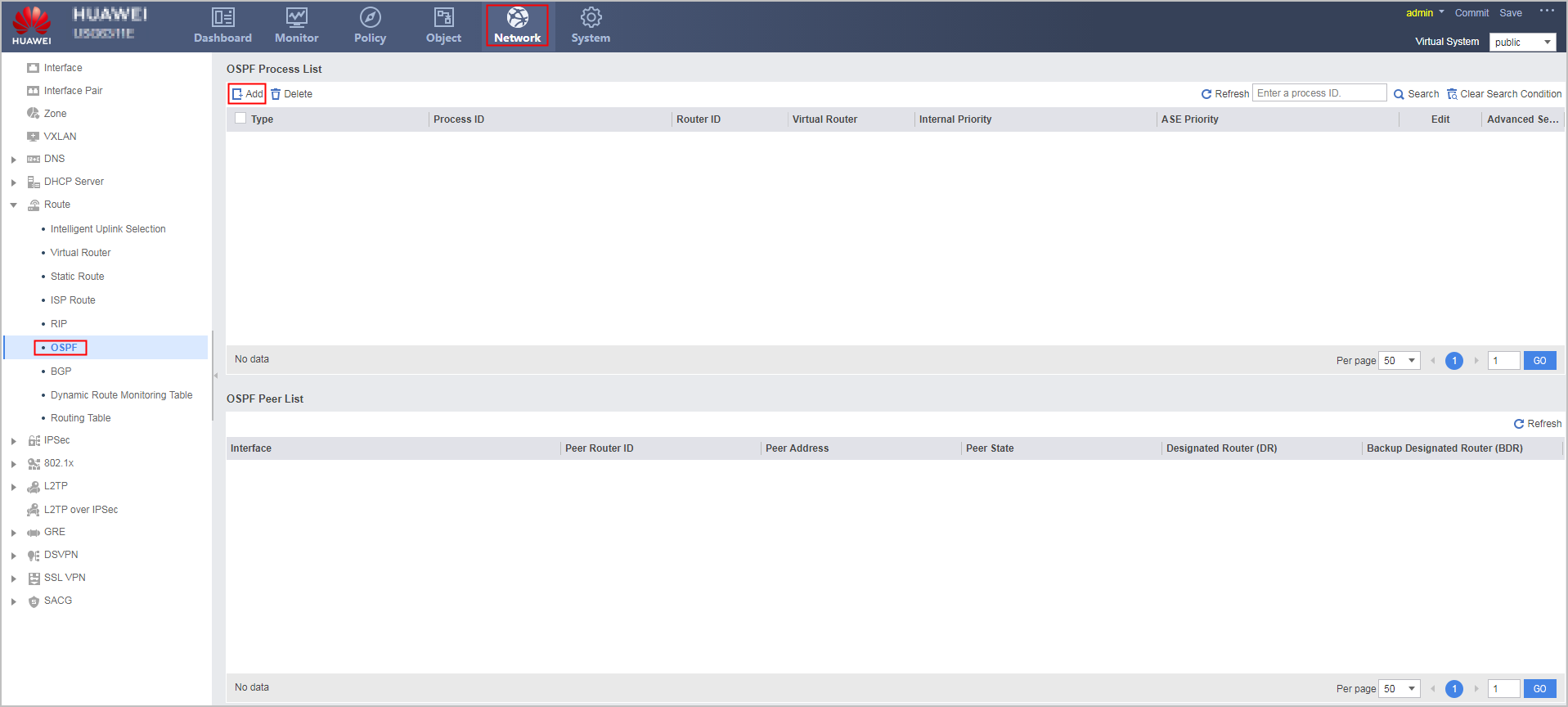
- Click Add to create an OSPF process.
- Configure the area where network segment 192.168.0.0
resides as Area 0.
- Click
 of the
created OSPF process.
of the
created OSPF process. - In the OSPFv2 process ID: 1 navigation tree, choose .
- Click Add and configure the area where
network segment 192.168.0.0 resides as Area 0.
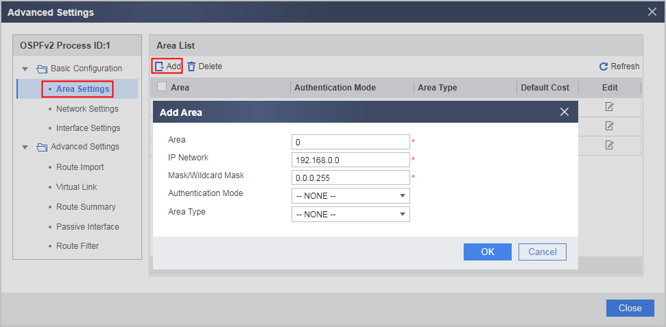
- Click OK.
- Click
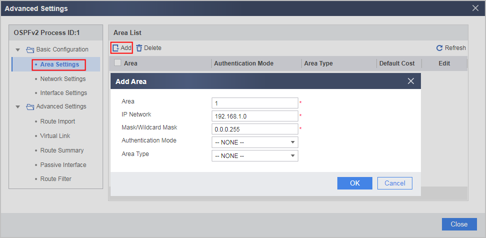
- Repeat the preceding steps to configure the area where
network segment 192.168.1.0 resides as Area 1.
- Choose .
- Configure FW_B.
- Configure basic OSPF functions of FW_B.
- Choose .
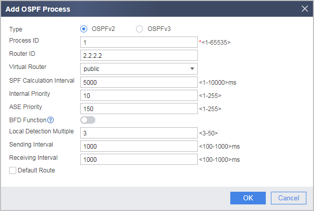
- Click Add to create an OSPF process.
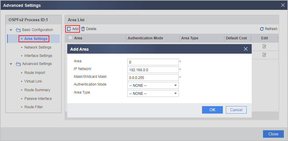
- Configure the area where network segment 192.168.0.0 resides as
Area 0.
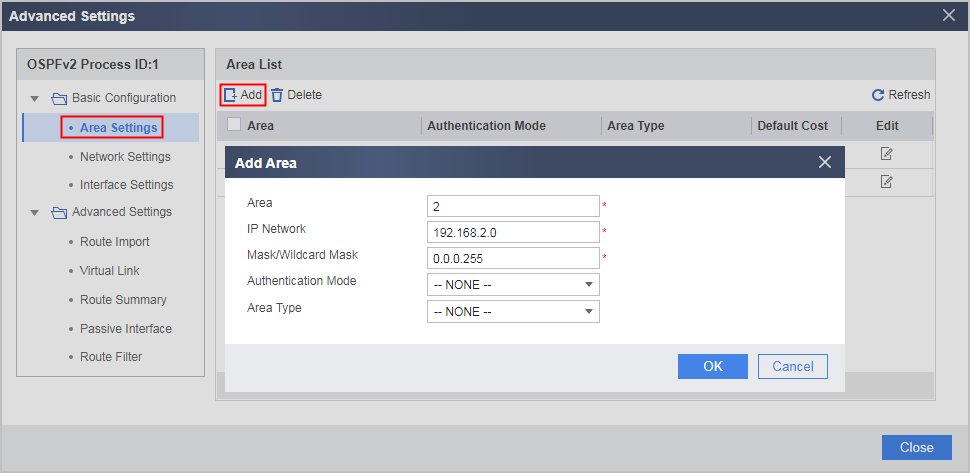
- Configure the area where network segment 192.168.2.0 resides as
Area 2.
- Click OK.
- Configure basic OSPF functions of FW_B.
- Configure FW_C.
- Configure basic OSPF functions of FW_C.
- Choose .
- Click Add to create an OSPF process.
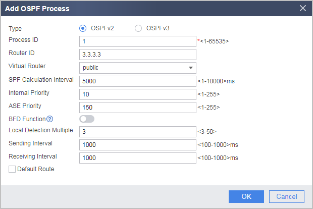
- Configure the area where network segments 192.168.1.0 and 172.16.1.0
reside as Area 1.
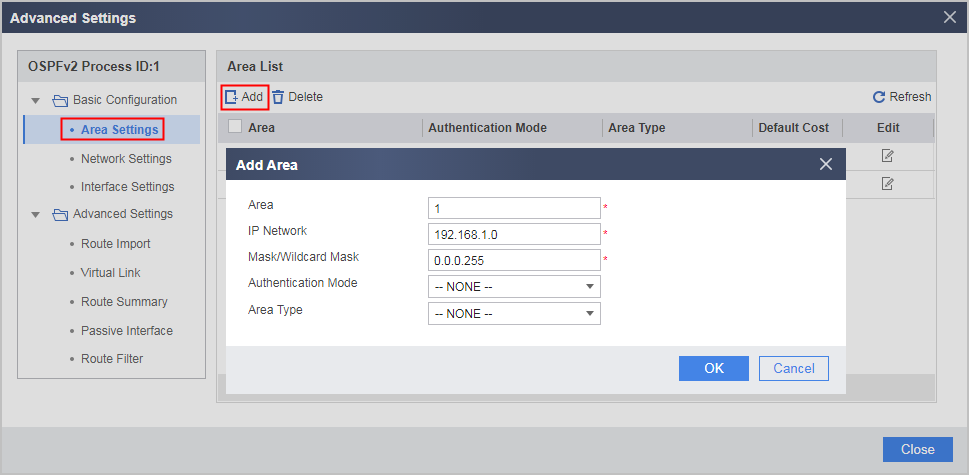

- Click OK.
- Configure basic OSPF functions of FW_C.
- Configure FW_D.
- Configure basic OSPF functions of FW_D.
- Choose .
- Click Add to create an OSPF process.
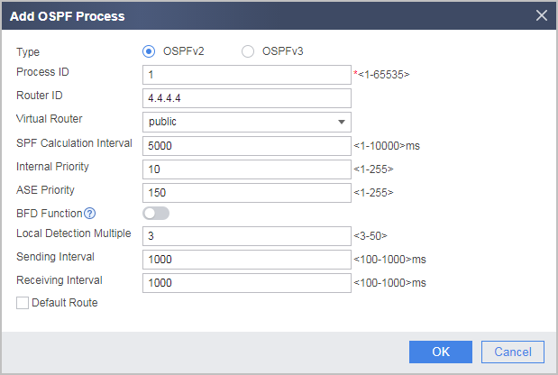
- Configure the area where network segments 192.168.2.0 and 172.17.1.0
reside as Area 2.
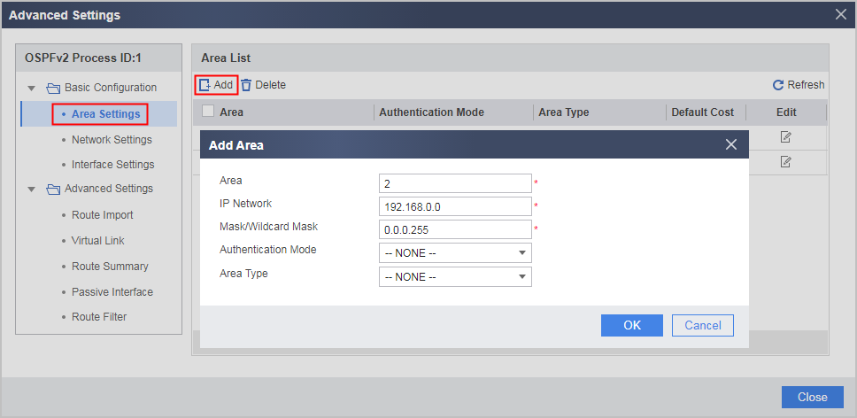
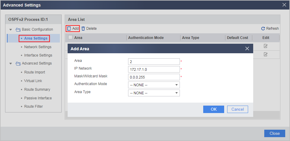
- Click OK.
- Configure basic OSPF functions of FW_D.
Configuration Verification
# Check the OSPF neighbors of FW_A.
[FW_A] display ospf peer

          OSPF Process 1 with Router ID 1.1.1.1
                  Neighbors

 Area 0.0.0.0 interface 192.168.0.1(GigabitEthernet0/0/1)'s neighbors
 Router ID: 2.2.2.2      Address: 192.168.0.2      GR State: Normal
   State: Full  Mode:Nbr is  Master  Priority: 1
   DR: None   BDR: None   MTU: 0
   Dead timer due in 36  sec
   Neighbor is up for 00:15:04
   Authentication Sequence: [ 0 ]

                  Neighbors

 Area 0.0.0.1 interface 192.168.1.1(GigabitEthernet0/0/2)'s neighbors
 Router ID: 3.3.3.3       Address: 192.168.1.2      GR State: Normal
   State: Full  Mode:Nbr is  Slave  Priority: 1
   DR: None   BDR: None   MTU: 0
   Dead timer due in 39  sec
   Neighbor is up for 00:07:32
   Authentication Sequence: [ 0 ]
# Check the OSPF routes of FW_A.
[FW_A] display ospf routing

          OSPF Process 1 with Router ID 1.1.1.1
                   Routing Tables

 Routing for Network
 Destination        Cost  Type       NextHop         AdvRouter       Area
 172.16.1.0/24      2  Stub       192.168.1.2     3.3.3.3      0.0.0.1
 172.17.1.0/24      3  Inter-area 192.168.0.2     2.2.2.2     0.0.0.0
 192.168.1.0/24     1  Transit    192.168.1.1     1.1.1.1     0.0.0.1
 192.168.2.0/24     2  Inter-area 192.168.0.2     2.2.2.2     0.0.0.0
 192.168.0.0/24     1  Transit    192.168.0.1     1.1.1.1     0.0.0.0

 Total Nets: 5
 Intra Area: 3  Inter Area: 2  ASE: 0  NSSA: 0
# Check the LSDB of FW_A.
[FW_A] display ospf lsdb

          OSPF Process 1 with Router ID 1.1.1.1
                  Link State Data Base

                          Area: 0.0.0.0
 Type      LinkState ID    AdvRouter          Age  Len   Sequence   Metric
 Router    2.2.2.2         2.2.2.2            317  48    80000003    1
 Router    1.1.1.1         1.1.1.1            316  48    80000003    1
 Sum-Net   172.16.1.0      1.1.1.1            250  28    80000002    2
 Sum-Net   172.17.1.0      2.2.2.2            203  28    80000002    2
 Sum-Net   192.168.2.0     2.2.2.2            237  28    80000003    1
 Sum-Net   192.168.1.0     1.1.1.1            295  28    80000003    1

                          Area: 0.0.0.1
Type      LinkState ID    AdvRouter          Age  Len   Sequence   Metric
 Router    3.3.3.3         3.3.3.3            217  60    80000006    1
 Router    1.1.1.1         1.1.1.1            289  48    80000003    1
 Sum-Net   172.17.1.0      1.1.1.1            202  28    80000002    3
 Sum-Net   192.168.2.0     1.1.1.1            242  28    80000002    2
 Sum-Net   192.168.0.0     1.1.1.1            300  28    80000002    1
# Check the routing table of FW_D and use the ping command to test the connectivity.
[FW_D] display ospf routing

          OSPF Process 1 with Router ID 4.4.4.4
                   Routing Tables

 Routing for Network
 Destination        Cost  Type       NextHop         AdvRouter       Area
 172.16.1.0/24      4  Inter-area 192.168.2.1     2.2.2.2         0.0.0.2
 172.17.1.0/24      1  Stub       172.17.1.1      4.4.4.4         0.0.0.2
 192.168.0.0/24     2  Inter-area 192.168.2.1     2.2.2.2         0.0.0.2
 192.168.1.0/24     3  Inter-area 192.168.2.1     2.2.2.2         0.0.0.2
 192.168.2.0/24     1  Transit    192.168.2.2     4.4.4.4         0.0.0.2

 Total Nets: 5
 Intra Area: 2  Inter Area: 3  ASE: 0  NSSA: 0
[FW_D] ping 172.16.1.1
  PING 172.16.1.1: 56  data bytes, press CTRL_C to break
    Reply from 172.16.1.1: bytes=56 Sequence=1 ttl=253 time=62 ms
    Reply from 172.16.1.1: bytes=56 Sequence=2 ttl=253 time=16 ms
    Reply from 172.16.1.1: bytes=56 Sequence=3 ttl=253 time=62 ms
    Reply from 172.16.1.1: bytes=56 Sequence=4 ttl=253 time=94 ms
    Reply from 172.16.1.1: bytes=56 Sequence=5 ttl=253 time=63 ms

  --- 172.16.1.1 ping statistics ---
    5 packet(s) transmitted
    5 packet(s) received
    0.00% packet loss
    round-trip min/avg/max = 16/59/94 ms
Configuration Scripts
Configuration script of FW_A
#
 sysname FW_A
#
router id 1.1.1.1
#
interface GigabitEthernet0/0/1
 undo shutdown
 ip address 192.168.0.1 255.255.255.0
#
firewall zone trust
add interface GigabitEthernet 0/0/1
#
interface GigabitEthernet0/0/2
 undo shutdown
 ip address 192.168.1.1 255.255.255.0
#
firewall zone trust
add interface GigabitEthernet 0/0/2
#
ospf 1
 area 0.0.0.0
  network 192.168.0.0 0.0.0.255
 area 0.0.0.1
  network 192.168.1.0 0.0.0.255
#
security-policy
  rule name policy_sec_1
    source-zone local
    source-zone trust
    destination-zone local
    destination-zone trust
    action permit
#
return
Configuration script of FW_B
#
 sysname FW_B
#
router id 2.2.2.2
#
interface GigabitEthernet0/0/1
 undo shutdown
 ip address 192.168.0.2 255.255.255.0
#
firewall zone trust
add interface GigabitEthernet 0/0/1
#
interface GigabitEthernet0/0/2
 undo shutdown
 ip address 192.168.2.1 255.255.255.0
#
firewall zone trust
add interface GigabitEthernet 0/0/2
#
ospf 1
 area 0.0.0.0
  network 192.168.0.0 0.0.0.255
 area 0.0.0.2
  network 192.168.2.0 0.0.0.255
#
security-policy
  rule name policy_sec_1
    source-zone local
    source-zone trust
    destination-zone local
    destination-zone trust
    action permit
#
return
Configuration script of FW_C
#
 sysname FW_C
#
router id 3.3.3.3
#
interface GigabitEthernet0/0/1
 undo shutdown
 ip address 192.168.1.2 255.255.255.0
#
firewall zone trust
add interface GigabitEthernet 0/0/1
#
interface GigabitEthernet0/0/3
 undo shutdown
 ip address 172.16.1.1 255.255.255.0
#
firewall zone trust
add interface GigabitEthernet 0/0/3
#
ospf 1
 area 0.0.0.1
  network 172.16.1.0 0.0.0.255
  network 192.168.1.0 0.0.0.255
#
security-policy
  rule name policy_sec_1
    source-zone local
    source-zone trust
    destination-zone local
    destination-zone trust
    action permit
#
return
Configuration script of FW_D
#
 sysname FW_D
#
router id 4.4.4.4
#
interface GigabitEthernet0/0/1
 undo shutdown
 ip address 192.168.2.2 255.255.255.0
#
firewall zone trust
add interface GigabitEthernet 0/0/1
#
interface GigabitEthernet0/0/3
 undo shutdown
 ip address 172.17.1.1 255.255.255.0
#
firewall zone trust
add interface GigabitEthernet 0/0/3
#
ospf 1
 area 0.0.0.2
  network 172.17.1.0 0.0.0.255
  network 192.168.2.0 0.0.0.255
#
security-policy
  rule name policy_sec_1
    source-zone local
    source-zone trust
    destination-zone local
    destination-zone trust
    action permit
#
return