CLI Example for Configuring OSPF Virtual Links
In certain cases, the direct physical connection between a backbone area and a non-backbone area can hardly be realized. In this case, you can configure OSPF virtual links for the ABR that is not directly connected to the backbone area.
Networking Requirements
As shown in Figure 1, Area 2 does not connect with the backbone area directly. Area 1 serves as a transit area to connect Area 2 and Area 0. A virtual link is configured between the FW_A and the FW_B.
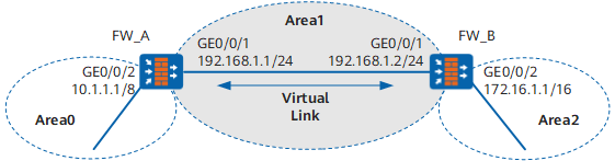
Configuration Roadmap
The configuration roadmap is as follows:
- Configuring basic OSPF functions on each FW
- Configuring the virtual connections on the FW_A and the FW_B to connect the backbone area with the non-backbone
Data Preparation
To complete the configuration, you need the following data:
- The OSPF router ID of the FW_A is 1.1.1.1. The number of its area is Area 0 and Area 1. Network segments 192.168.1.0/24 and 10.0.0.0/8 are configured with OSPF.
- The OSPF router ID of the FW_B is 2.2.2.2. The number of its area is Area 1 and Area 2. Network segments 192.168.1.0/24 and 172.16.0.0/16 are configured with OSPF.
Procedure
- Set the IP addresses for the interfaces, add the interfaces to security zones, and configure the interzone security policy.
# Configure the FW_A.
<FW> system-view
[FW] sysname FW_A
[FW_A] interface GigabitEthernet 0/0/1
[FW_A-GigabitEthernet0/0/1] ip address 192.168.1.1 24
[FW_A-GigabitEthernet0/0/1] quit
[FW_A] interface GigabitEthernet 0/0/2
[FW_A-GigabitEthernet0/0/2] ip address 10.1.1.1 8
[FW_A-GigabitEthernet0/0/2] quit
[FW_A] firewall zone trust
[FW_A-zone-trust] add interface GigabitEthernet 0/0/1
[FW_A-zone-trust] add interface GigabitEthernet 0/0/2
[FW_A-zone-trust] quit
[FW_A] security-policy
[FW_A-policy-security] rule name policy_sec_1
[FW_A-policy-security-rule-policy_sec_1] source-zone trust local
[FW_A-policy-security-rule-policy_sec_1] destination-zone local trust
[FW_A-policy-security-rule-policy_sec_1] action permit
[FW_A-policy-security-rule-policy_sec_1] quit
# Configure the FW_B.
<FW> system-view
[FW] sysname FW_B
[FW_B] interface GigabitEthernet 0/0/1
[FW_B-GigabitEthernet0/0/1] ip address 192.168.1.2 24
[FW_B-GigabitEthernet0/0/1] quit
[FW_B] interface GigabitEthernet 0/0/2
[FW_B-GigabitEthernet0/0/2] ip address 172.16.1.1 16
[FW_B-GigabitEthernet0/0/2] quit
[FW_B] firewall zone trust
[FW_B-zone-trust] add interface GigabitEthernet 0/0/1
[FW_B-zone-trust] add interface GigabitEthernet 0/0/2
[FW_B-zone-trust] quit
[FW_B] security-policy
[FW_B-policy-security] rule name policy_sec_1
[FW_B-policy-security-rule-policy_sec_1] source-zone trust local
[FW_B-policy-security-rule-policy_sec_1] destination-zone local trust
[FW_B-policy-security-rule-policy_sec_1] action permit
[FW_B-policy-security-rule-policy_sec_1] quit
- Configure OSPF.
# Enable OSPF on the FW_A and set the router ID for the FW_A to 1.1.1.1.
[FW_A] ospf 1 router-id 1.1.1.1# Configure network segment 10.0.0.0 as Area 0.
[FW_A-ospf-1] area 0
[FW_A-ospf-1-area-0.0.0.0] network 10.0.0.0 0.255.255.255
# Return to the OSPF view.
[FW_A-ospf-1-area-0.0.0.0] quit# Configure network 192.168.1.0 as Area 1.
[FW_A-ospf-1] area 1
[FW_A-ospf-1-area-0.0.0.1] network 192.168.1.0 0.0.0.255
# Return to the OSPF view.
[FW_A-ospf-1-area-0.0.0.1] quit# Enable OSPF on the FW_B and set the router ID for the FW_B to 2.2.2.2.
[FW_B] ospf 1 router-id 2.2.2.2# Configure network segment 192.168.1.0 as Area 1.
[FW_B-ospf-1] area 1
[FW_B-ospf-1-area-0.0.0.1] network 192.168.1.0 0.0.0.255
# Return to the OSPF view.
[FW_B-ospf-1-area-0.0.0.1] quit# Configure network segment 172.16.0.0 as Area 2.
[FW_B-ospf-1] area 2
[FW_B-ospf-1-area-0.0.0.2] network 172.16.0.0 0.0.255.255
# Return to the OSPF view.
[FW_B-ospf-1-area-0.0.0.2] quit# Display the OSPF routing table of the FW_A.
<FW_A> display ospf routing

          OSPF Process 1 with Router ID 1.1.1.1
                   Routing Tables

 Routing for Network
 Destination        Cost  Type       NextHop         AdvRouter       Area
 10.0.0.0/8         1     Stub       10.1.1.1        1.1.1.1         0.0.0.0
 192.168.1.0/24     1     Transit    192.168.1.1     1.1.1.1         0.0.0.1

 Total Nets: 2
 Intra Area: 2  Inter Area: 0  ASE: 0  NSSA: 0
Area 2 does not connect directly to Area 0. Thus, there is no Area 2 route in the routing table of the FW_A.
- Configure the virtual link.
# Enable OSPF on the FW_A.
[FW_A] ospf# Configure a virtual link with the peer router ID 2.2.2.2.
[FW_A-ospf-1] area 1
[FW_A-ospf-1-area-0.0.0.1] vlink-peer 2.2.2.2
# Return to the OSPF view.
[FW_A-ospf-1-area-0.0.0.1] quit# Enable OSPF on the FW_B.
[FW_B] ospf# Configure a virtual link with the peer router ID 1.1.1.1.
[FW_B-ospf-1] area 1
[FW_B-ospf-1-area-0.0.0.1] vlink-peer 1.1.1.1
# Return to the OSPF view.
[FW_B-ospf-1-area-0.0.0.1] quit# Display the OSPF routing table of the FW_A.
[FW_A] display ospf routing

          OSPF Process 1 with Router ID 1.1.1.1
                   Routing Tables

 Routing for Network
 Destination        Cost  Type       NextHop         AdvRouter       Area
 172.16.1.1/32      2     Inter-area 192.168.1.2     2.2.2.2         0.0.0.0
 10.0.0.0/8         1     Stub       10.1.1.1        1.1.1.1         0.0.0.0
 192.168.1.0/24     1     Transit    192.168.1.1     1.1.1.1         0.0.0.1

 Total Nets: 3
 Intra Area: 2  Inter Area: 1  ASE: 0  NSSA: 0
Configuration Script
Configuration script of FW_A
#
 sysname FW_A
#
interface GigabitEthernet0/0/1
 undo shutdown
 ip address 192.168.1.1 255.255.255.0
#
interface GigabitEthernet0/0/2
 undo shutdown
 ip address 10.1.1.1 255.0.0.0
#
firewall zone trust
 set priority 85
 add interface GigabitEthernet0/0/1
 add interface GigabitEthernet0/0/2
#
security-policy
 rule name policy_sec_1
  source-zone local
  source-zone trust
  destination-zone local
  destination-zone trust
  action permit
#
ospf 1 router-id 1.1.1.1
 area 0.0.0.0
  network 10.0.0.0 0.255.255.255
 area 0.0.0.1
  network 192.168.1.0 0.0.0.255
  vlink-peer 2.2.2.2
#
return
Configuration script of FW_B
#
 sysname FW_B
#
interface GigabitEthernet0/0/1
 undo shutdown
 ip address 192.168.1.2 255.255.255.0
#
interface GigabitEthernet0/0/2
 undo shutdown
 ip address 172.16.1.1 255.255.0.0
#
firewall zone trust
 set priority 85
 add interface GigabitEthernet0/0/1
 add interface GigabitEthernet0/0/2
#
security-policy
 rule name policy_sec_1
  source-zone local
  source-zone trust
  destination-zone local
  destination-zone trust
  action permit
#
ospf 1 router-id 2.2.2.2
 area 0.0.0.1
  network 192.168.1.0 0.0.0.255
  vlink-peer 1.1.1.1
 area 0.0.0.2
  network 172.16.0.0 0.0.255.255
#
return