Enabling Communication Between a Virtual System and the Public System
This section describes how to configure routes and security policies for the communication between a virtual system and the public system.
Context
To enable the communication between the virtual system and public system, you need to correctly configure the routes and security policies on the virtual system and public system, just as on two physical devices.
Before the actual configuration, you are advised to read Communication Between a Virtual System and the Public System and learn about the mechanism for the communication between a virtual system and the public system.
As shown in Figure 1, routes and security policies must be configured to enable the users of vsysa to access the Internet server at IP address 3.3.3.3 through public interface GE0/0/1 of the public system.
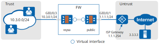

The preceding configuration allows only the unidirectional communication from vsysa to public.
If hosts in public need to access hosts in vsysa, you must configure the routes and security policies from public to vsysa.
Procedure
- Configure routes and security policies on vsysa.
- Click
 next to the Virtual-if1 interface to set
an IP address, add the interface to the Untrust zone. The IP address
can be any value as long as it does not conflict with the IP address
on any other interface.
next to the Virtual-if1 interface to set
an IP address, add the interface to the Untrust zone. The IP address
can be any value as long as it does not conflict with the IP address
on any other interface.
The ID of a virtual interface is automatically assigned based on existing IDs in the system. Therefore, in actual configurations, the interface might not be Virtual-if1. You can view the mapping between the virtual system and virtual interface in Interface List.
- Click
- Configure routes and security policies on the public system.
- Click Add and configure a default
route to the Internet as follows:
Protocol Type
IPv4
Source Virtual Router
public
Destination Address/Mask
0.0.0.0/0.0.0.0
Destination Virtual Router
public
Next Hop
1.1.1.254
Interface
-
In this example, only users in vsysa need to access the server in root system. Therefore, you only need to configure the unidirectional route from vsysa to root system. The reply packets from the server will match the session table of root system and be directly forwarded to vsysa. This configuration is different from the route configuration for forwarding within one virtual system.
If users in the root system need to access hosts in vsysa, you must configure a static route from the root system to vsysa. Set Source Virtual Router of the route to public, Destination Address/Mask to 10.3.0.0/24, and Destination Virtual Router to vsysa.
- Click next to the Virtual-if0 interface to set
an IP address, add the interface to the Trust zone. The IP address
can be any value as long as it does not conflict with the IP address
on any other interface.
- Click Add and configure a default
route to the Internet as follows: