CLI: Example for Applying Port Pre-Allocation and Incremental Allocation to the NAT444 Scenario
This section provides an example for configuring the port pre-allocation and incremental allocation function in the NAT444 scenario.
Networking Requirements
To adapt to network development, carrier A needs to plan the network segment to:
- Save public address resources.
- Properly allocate ports.
- Trace user addresses expediently.
The carrier uses the network plan shown in Figure 1 to meet the preceding requirements. The network plan is as follows:
To save public IPv4 addresses, allocate private addresses to IPv4 users. Configure the NAT function twice on the CPE and CGN to enable users on the private IPv4 network to access the IPv4 Internet.
To properly allocate ports, configure a NAT policy to provide the port pre-allocation and incremental allocation function on the CGN. In this way, the service traffic from the CPE uses the pre-allocated or incrementally allocated ports.
To trace user addresses, configure the syslog server to interwork with the CGN. The CGN generates logs on port allocation and reclamation. The syslog server parses the logs to obtain source addresses and port ranges to trace the user addresses.
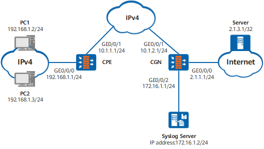
Data Planning
Item |
Data |
Remarks |
|
|---|---|---|---|
CPE |
GE0/0/0 Trust |
Private IPv4 address: 192.168.1.1/24 |
The CPE connects to private IPv4 address users. |
GigabitEthernet 0/0/1 Untrust |
Private IPv4 address of the carrier: 10.1.1.1/24 |
The interface connects to the MAN of the carrier. Assume that the next-hop address of the path to the MAN is 10.1.1.2. |
|
Address pool |
The address of GigabitEthernet 0/0/1 is used as the translated address. |
The address pool is used to translate IPv4 addresses of the user's private network to the IPv4 address of the carrier's private network. |
|
CGN |
GE0/0/0 Untrust |
Public IPv4 address: 2.1.1.1/24 |
GE0/0/0 connects to the IPv4 Internet. Assume that the next-hop address is 2.1.1.2/24. |
GigabitEthernet 0/0/1 Trust |
IPv4 address of the carrier's private network: 10.1.2.1/24 |
GigabitEthernet 0/0/1 connects to the MAN of the carrier. Assume that the next-hop address of the path to the MAN is 10.1.2.2. |
|
GigabitEthernet 0/0/2 DMZ |
IP address: 172.16.1.1/24 |
GigabitEthernet 0/0/2 is used to interwork with the syslog server. |
|
Address pool |
Addresses in the address pool: 1.1.2.1 to 1.1.2.5 |
The address pool is used to translate the private IPv4 addresses of the carrier to public IPv4 addresses. |
|
PC1 |
Private IPv4 address: 192.168.1.2/24 |
- |
|
PC2 |
Private IPv4 address: 192.168.1.3/24 |
- |
|
Internet Server |
Public IPv4 address: 2.1.3.1/32 |
- |
|
Syslog server |
IPv4 address: 172.16.1.2/24 |
The syslog server parses log packets to trace user (CPE) addresses. |
|
Procedure
- Configure the CPE.
- Configure the CGN.
- Configure the hash-based CPU selection mode to be oriented to source IP address.
<FW> system-view
[FW] sysname CGN
[CGN] firewall hash-mode source-only

The modified hash mode takes effect only after the device is restarted.
- Configure the hash-based CPU selection mode to be oriented to source IP address.
- Configure the Internet server.
In common cases, the ISP configures servers. This section describes only the following key points for the server configuration:
- Set the IP address to 2.1.3.1/32 for the server.
- The server must maintain a route to an address in the address pool on the CGN.
- Configure PC1 and PC2 on the intranet.
Configure the gateway address to 192.168.1.1 for PC1 and PC2 on the intranet.
- Configure the syslog server.
The configuration varies according to the version of the syslog server. For details, refer to related documents delivered with the syslog server.
Verification
# After you complete the preceding configurations, configure PC1 to ping the IP address of the server.
C:\Documents and Settings\Administrator>ping 2.1.3.1

Pinging 2.1.3.1 with 32 bytes of data:

Reply from 2.1.3.1: bytes=32 time=9ms TTL=253
Reply from 2.1.3.1: bytes=32 time<1ms TTL=253
Reply from 2.1.3.1: bytes=32 time<1ms TTL=253
Reply from 2.1.3.1: bytes=32 time<1ms TTL=253

Ping statistics for 2.1.3.1:
    Packets: Sent = 4, Received = 4, Lost = 0 (0% loss),
Approximate round trip times in milli-seconds:
    Minimum = 0ms, Maximum = 9ms, Average = 2ms
Run the display cpe-user information cpe-ipv4 10.1.1.1 command in any view of the CGN to check the details about the CPE user at 10.1.1.1.
[CGN] display cpe-user information cpe-ipv4 10.1.1.1 slot 6 cpu 0
 This operation will take a few minutes. Press 'Ctrl+C' to break ...
 UserTbl item(s) on slot 6 cpu 0
 --------------------------------------------------------------------
 Scene: NAT444  DstZone: untrust CPEIP: 10.1.1.1
 TTL: 40   LeftTime: 34 Increase Count: 0  VPN: public
 PoolID: addressgroup1  SectionID: 1  PublicIP: 1.1.2.2  StartPort: 2048
 PortNumber: 256  PortTotal: 256  Used Port Number: 0
As shown in the preceding command output, the source addresses of service flows sent by the CPE at 10.1.1.1 are translated into 1.1.2.2. The port range is from 2048 to 2303, containing 256 ports.
Configure PC2 to ping the IP address of the server. Run the display cpe-user information cpe-ipv4 10.1.1.1 command in any view of the CGN to check the details about the CPE user at 10.1.1.1. The translated addresses and port range remain unchanged.
During port pre-allocation and incremental allocation, the syslog server receives a log. The log is displayed as follows on the syslog server (In this example, the log is displayed when the port is pre-allocated at first time and the syslog format is France Telecom. If the syslog needs to be displayed in the China Telecom format, the nat port-block syslog descriptive format cn command needs to be run in system view.)
NAT444userbased - %%01SEC/6/BIND(l): An initial portrange is assigned, in nat444 scene. privateip='10.1.1.1' srcvrfid='0' publicip='1.1.2.2' publicportrange='2048~2303' time='2012-05-02 18:24:09'.
The log displays the IP address of the CPE, translated IP address, port range, and time stamp for address source tracing.
Configuration Scripts
The CPE configuration script is as follows:
#
 sysname CPE
#
interface GigabitEthernet0/0/0
 ip address 192.168.1.1 255.255.255.0
#
interface GigabitEthernet 0/0/1
 ip address 10.1.1.1 255.255.255.0
#
firewall zone trust
 set priority 85
 add interface GigabitEthernet0/0/0
#
firewall zone untrust
 set priority 5
 add interface GigabitEthernet 0/0/1
#
 ip route-static 10.1.2.0 255.255.255.0 10.1.1.2
#
security-policy
  rule name policy_sec_1
    source-zone trust
    destination-zone untrust
    source-address 192.168.1.0 24
    action permit
#
nat-policy
  rule name policy_nat_1
    source-zone trust
    destination-zone untrust
    source-address 192.168.1.0 24
    action source-nat easy-ip
#
return
The CGN configuration script is as follows:
#
 sysname CGN
#                                                                                firewall hash-mode source-only
#
interface GigabitEthernet0/0/0
 ip address 2.1.1.1 255.255.255.0
#
interface GigabitEthernet 0/0/1
 ip address 10.1.2.1 255.255.255.0
#
interface GigabitEthernet 0/0/2
 ip address 172.16.1.1 255.255.255.0
#
firewall zone trust
 set priority 85
 add interface GigabitEthernet 0/0/1
#
firewall zone dmz
 set priority 50
 add interface GigabitEthernet 0/0/2
#
firewall zone untrust
 set priority 5
 add interface GigabitEthernet0/0/0
#
 ip route-static 10.1.1.0 255.255.255.0 10.1.2.2
 ip route-static 1 1.3.1.255.255.255.255 2.1.1.2
#
 nat port-block assigning syslog enable
 nat port-block freeing syslog enable
 nat port-block syslog host 172.16.1.2 source CGN 172.16.1.1 514
#
 nat address-group addressgroup1
   port-block-size 256
   route enable
   section 1 1.1.2.1 1.1.2.5
#
security-policy
  rule name policy_sec_1
    source-zone trust
    destination-zone untrust
    source-address 10.1.1.0 24
    action permit
  rule name policy_sec_2
    source-zone local
    destination-zone dmz
    source-address destination-address 172.16.1.0 24
    action permit
#
nat-policy
  rule name policy_nat_1
    source-zone trust
    destination-zone untrust
    source-address 10.1.1.0 24
    action source-nat address-group addressgroup1
#
return