Web: Example for Configuring Cross-NAT DSVPN
Networking Requirements
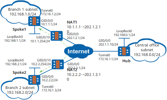
An enterprise has an HQ network (Hub) and multiple branch networks (Spoke1 and Spoke2 are involved in this example). Branch networks are distributed in different locations and the subnet environment of branch networks frequently changes. After the address of a branch network experiences NAT, the branch network can access the public network. The live network of the enterprise uses OSPF.
Configuration Roadmap
Because branch networks access the public network after experiencing NAT, branch networks are not clear about the public network addresses of each other after NAT, a cross-NAT DSVPN is required for VPN interconnection between branch networks.
Because the quantity of branch networks is large, the DSVPN in the shortcut scenario is recommended.
Because the subnet environment of branch and HQ networks frequently changes, OSPF is recommended for communications between the branch networks and the HQ network to simplify maintenance according to enterprise network planning.
Procedure
- Configure the IP address of each interface of the FW, and add the interfaces to the corresponding security zone.
Configure the IP address and security zone for the Hub interface.
- Choose .
- Click
 of GE0/0/0 and set the parameters as follows:
Zone
untrust
IPv4
IP Address
1.1.1.10/24
- Click OK.
- Choose .
- Click Add and set the following parameters.
Interface Name
Loopback0
Type
Local loopback interface
IPv4
IP Address
192.168.0.1/24
- Click OK.
Configure IP addresses of other device interfaces based on the Figure 1 configuration. IP addresses of the public network interfaces of NAT1 and NAT2 are dynamically obtained (DHCP mode). The configuration process is similar to that of the Hub network and is not further described here.
- Configure the public network route from the FW and the Internet, and ensure that the public network routes between devices are accessible.
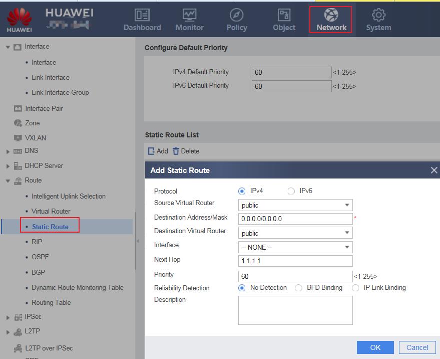
This section describes the method for configuring a public network route destined for the Internet using the Hub network as an example. The configuration methods of other devices are similar.
- Choose .
- Click Add and set the following parameters. Assume that the next-hop address from the Hub network to the Internet is 1.1.1.1.
Destination IP Address/Mask
0.0.0.0/0.0.0.0
Next Hop
1.1.1.1
- Click OK.
- Configure the NAT function.
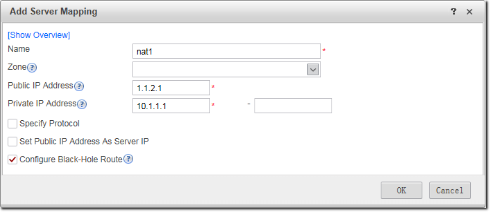
Configure the NAT function for NAT1.
- Choose .
- Click Add and set the parameters as follows:
- Click OK.
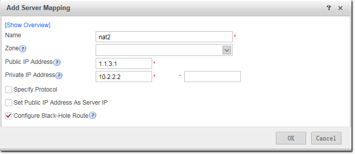
Configure the NAT function for NAT2.
- Choose .
- Click Add and set the parameters as follows:
- Click OK.
- Set DSVPN parameters.Configure the Hub.
- Choose .
- Click Add and set the following parameters. Set the authentication key to Test@123.
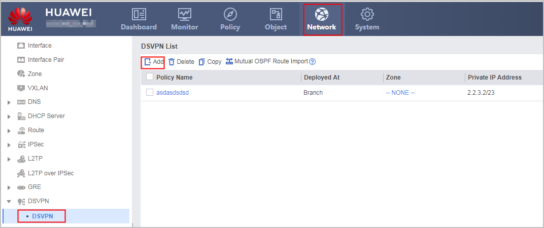
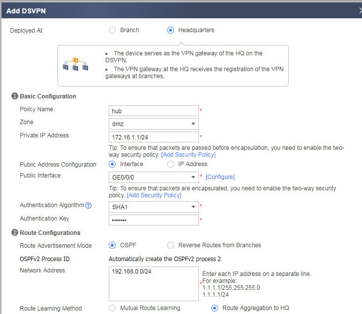
- Click OK.
Configure Spoke1.- Choose .
- Click Add and set the following parameters. Set the authentication key to Test@123.
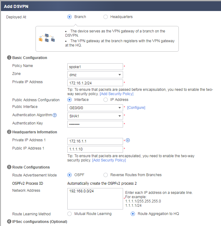
- Click OK.
Configure Spoke2.- Choose .
- Click Add and set the following parameters. Set the authentication key to Test@123.
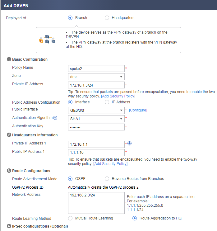
- Click OK.
- Configure security policies on each device.In this example, the Loopback interface (in the Local zone) is used to simulate an internal subnet user of an enterprise. Therefore, the security policy for accessing the security zone (DMZ) of the Tunnel interface from the Local zone must be enabled. In actual situations, you can enable security policies according to the real security zone where the internal subnet of the enterprise is located. For example, if the internal subnet of the enterprise is located in the trust zone, you can enable the security policy for the access from the trust zone to the DMZ. This section describes the method for configuring security policies using Spoke1 as an example.
- Choose .
- Click Add and configure security policy policy1.
Name
policy1
Source Zone
local,dmz
Destination Zone
local,dmz
Action
Permit
- Click OK.
- Configure the security policy for the access from the Local zone to the Untrust zone, and allow GRE-encapsulated packets to pass through the security policy check.
Name
policy2
Source Zone
local,untrust
Destination Zone
local,untrust
Service
gre,ospf
Action
Permit
Verification
- Enable subnet users of branch network 1 and branch network 2 to mutually access each other.
- Choose . The tunnel between the current device and another branch network or between the current device and the HQ network is established.
Configuration Scripts
Configuration script of the Hub:
#
interface GigabitEthernet0/0/0
 ip address 1.1.1.10 255.255.255.0
#
interface Loopback0
 ip address 192.168.0.1 255.255.255.0
#
interface Tunnel1
 description hub
 ip address 172.16.1.1 255.255.255.0
 tunnel-protocol gre p2mp
 source GigabitEthernet0/0/0
 ospf network-type p2mp
 ospf dr-priority 2
 alias hub
 nhrp authentication hash sha1 %^%#JIo#MH#;W5]17p.1[]t(<*tb.txS('1iT|Dq>,!:%^%#
 nhrp redirect
 nhrp entry multicast dynamic
#
ospf 1
 area 0.0.0.0
  network 172.16.1.0 0.0.0.255
 area 0.0.0.1
  network 192.168.0.0 0.0.0.255
#
firewall zone untrust
 set priority 5
 add interface GigabitEthernet0/0/0
#
firewall zone dmz
 set priority 50
 add interface Tunnel 1
#
security-policy
 rule name policy1
  source-zone local
  source-zone dmz
  destination-zone local
  destination-zone dmz
  action permit
 rule name policy2
  source-zone local
  source-zone untrust
  destination-zone local
  destination-zone untrust
  service gre
  service ospf
  action permit
#
return
Configuration script of Spoke1:
#
interface GigabitEthernet0/0/0
 ip address 10.1.1.1 255.255.255.0
#
interface Loopback0
 ip address 192.168.1.1 255.255.255.0
#
interface Tunnel1
 description spoke
 ip address 172.16.1.2 255.255.255.0
 tunnel-protocol gre p2mp
 source GigabitEthernet0/0/0
 ospf network-type p2mp
 alias spoke1
 nhrp authentication hash sha1 %^%#JIo#MH#;W5]17p.1[]t(<*tb.txS('1iT|Dq>,!:%^%#
 nhrp shortcut
 nhrp entry multicast dynamic
 nhrp entry 172.16.1.1 1.1.1.10 register preference 10
#
ospf 1
 area 0.0.0.0
  network 172.16.1.0 0.0.0.255
 area 0.0.0.1
  network 192.168.1.0 0.0.0.255
#
firewall zone untrust
 set priority 5
 add interface GigabitEthernet0/0/0
#
firewall zone dmz
 set priority 50
 add interface Tunnel 1
#
security-policy
 rule name policy1
  source-zone local
  source-zone dmz
  destination-zone local
  destination-zone dmz
  action permit
 rule name policy2
  source-zone local
  source-zone untrust
  destination-zone local
  destination-zone untrust
  service gre
  service ospf
  action permit
#
return
Configuration script of Spoke2:
#
#
interface GigabitEthernet0/0/0
 ip address 10.2.2.2 255.255.255.0
#
interface Loopback0
 ip address 192.168.2.1 255.255.255.0
#
interface Tunnel1
 description spoke
 ip address 172.16.1.3 255.255.255.0
 tunnel-protocol gre p2mp
 source GigabitEthernet0/0/0
 ospf network-type p2mp
 alias spoke2
 nhrp authentication hash sha1 %^%#JIo#MH#;W5]17p.1[]t(<*tb.txS('1iT|Dq>,!:%^%#
 nhrp shortcut
 nhrp entry multicast dynamic
 nhrp entry 172.16.1.1 1.1.1.10 register preference 10
#
ospf 1
 area 0.0.0.0
  network 172.16.1.0 0.0.0.255
 area 0.0.0.1
  network 192.168.1.0 0.0.0.255
#
firewall zone untrust
 set priority 5
 add interface GigabitEthernet0/0/0
#
firewall zone dmz
 set priority 50
 add interface Tunnel 1
#
security-policy
 rule name policy1
  source-zone local
  source-zone dmz
  destination-zone local
  destination-zone dmz
  action permit
 rule name policy2
  source-zone local
  source-zone untrust
  destination-zone local
  destination-zone untrust
  service gre
  service ospf
  action permit
#
return
-
#
#
interface GigabitEthernet0/0/0
 dhcp client enable
#
interface GigabitEthernet0/0/10
 ip address 10.1.1.254 255.255.255.0
#
firewall zone untrust
 set priority 5
 add interface GigabitEthernet0/0/0
#
firewall zone trust
 set priority 85
 add interface GigabitEthernet0/0/10
#
security-policy
 rule name policy1
  source-zone trust
  source-zone untrust
  destination-zone trust
  destination-zone untrust
  action permit
#
nat server nat1 global 1.1.2.1 inside 10.1.1.1 no-reverse unr-route
#
return
-
#
#
interface GigabitEthernet0/0/0
 dhcp client enable
#
interface GigabitEthernet0/0/10
 ip address 10.2.2.254 255.255.255.0
#
firewall zone untrust
 set priority 5
 add interface GigabitEthernet0/0/0
#
firewall zone trust
 set priority 85
 add interface GigabitEthernet0/0/10
#
security-policy
 rule name policy1
  source-zone trust
  source-zone untrust
  destination-zone trust
  destination-zone untrust
  action permit
#
nat server nat2 global 1.1.3.1 inside 10.2.2.2 no-reverse unr-route
#
return