Web: Example for Configuring Hot Standby in Load Balancing Mode Where Firewalls Are Deployed in In-path Mode and Connect to Routers in Upstream and Downstream Directions
This section provides a web example of configuring hot standby in load balancing mode in which the service interfaces of the firewalls work at Layer 3 and connect to routers in upstream and downstream directions.
Networking Requirements
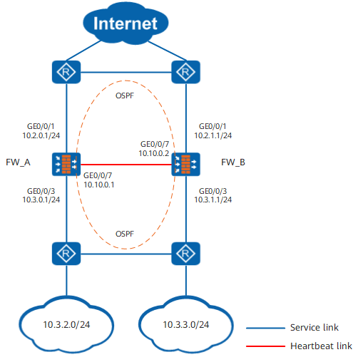
On the network shown in Figure 1, the service interfaces of two FWs work at Layer 3 and are directly connected to routers. The FWs and directly connected routers run OSPF.
The FWs are expected to work in load balancing mode. Normally, both FW_A and FW_B forward traffic. When one FW goes faulty, the other FW takes over all the traffic load.
Procedure
- Configure interfaces and basic network configurations.
- Configure OSPF to ensure IP connectivity.
- Configure OSPF on FW_A.
- Choose and click Add.

Create an OSPF process, set the parameters as follows, and click OK.
Type
OSPFv2
Process ID
10
- Click
 , click Add, create an OSPF area and set the parameters as follows, and then click OK.
Area
0.0.0.0
IP Network
10.2.0.0
Mask/Wildcard Mask
255.255.255.0
- Choose , click Add, create a network and set the parameters as follows, and then click OK.
Area
0.0.0.0
IP Network
10.3.0.0
Mask/Wildcard Mask
255.255.255.0
- Choose and click Add.
- Configure OSPF on FW_B.
- Choose and click Add.
Create an OSPF process, set the parameters as follows, and click OK.
Type
OSPFv2
Process ID
10
- Click , click Add, create an OSPF area and set the parameters as follows, and then click OK.
Area
0.0.0.0
IP Network
10.2.1.0
Mask/Wildcard Mask
255.255.255.0
Choose , click Add, create a network and set the parameters as follows, and then click OK.
Area
0.0.0.0
IP Network
10.3.1.0
Mask/Wildcard Mask
255.255.255.0
- Configure OSPF on FW_A.
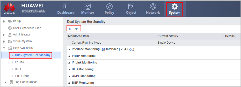
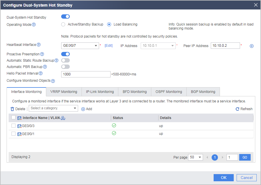
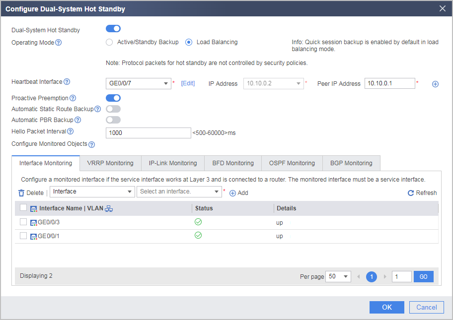
- Configure hot standby.
- Configure the security policies.
Security policies configured on FW_A are automatically backed up to FW_B.
- Click Add Security Policy, configure security policy policy_sec and set the parameters as follows, and then click OK.
# Configure security policies to allow FWs and the upstream/downstream routers to exchange OSPF packets.

Controlling function of security policies for OSPF packets are configured by the firewall packet-filter basic-protocol enable command. By default, the function of the firewall packet-filter basic-protocol enable command is enabled. That is, OSPF packets are controlled by security policies. In this case, a security policy must be configured between the security zones where the upstream/downstream service interfaces reside and the local zone to allow OSPF packets to pass. In this example, enabling the firewall packet-filter basic-protocol enable command is used as an example.
Name
policy_ospf_1
Source Zone
local
Destination Zone
trust,untrust
Service
ospf
Action
Permit
Name
policy_ospf_2
Source Zone
trust,untrust
Destination Zone
local
Service
ospf
Action
Permit
# Configure a security policy to allow intranet users to access the Internet.
Name
policy_sec
Source Zone
trust
Destination Zone
untrust
Source Address/Region
10.3.2.0/24,10.3.3.0/24
Action
Permit
- Click Add Security Policy, configure security policy policy_sec and set the parameters as follows, and then click OK.
Configuration Verification
Choose to view the operating status of hot standby.
- Normally, the Current Running Mode of FW_A is Load Balancing and the Current Status is Active. The Current Running Mode of FW_B is Load Balancing and the Current Status is Active. This shows that traffic is forwarded by FW_A.
- When FW_A goes faulty, the Current Running Mode of FW_A is Active/Standby Backup and the Current Status is Standby. The Current Running Mode of FW_B is Active/Standby Backup and the Current Status is Active. This shows that traffic is forwarded by FW_B.
Configuration Scripts
FW_A |
FW_B |
|---|---|
# hrp enable hrp interface GigabitEthernet 0/0/7 remote 10.10.0.2 hrp mirror session enable hrp track interface GigabitEthernet 0/0/1 hrp track interface GigabitEthernet 0/0/3 # interface GigabitEthernet 0/0/1 ip address 10.2.0.1 255.255.255.0 # interface GigabitEthernet 0/0/3 ip address 10.3.0.1 255.255.255.0 # interface GigabitEthernet 0/0/7 ip address 10.10.0.1 255.255.255.0 # firewall zone trust set priority 85 add interface GigabitEthernet 0/0/3 # firewall zone untrust set priority 5 add interface GigabitEthernet 0/0/1 # firewall zone dmz set priority 50 add interface GigabitEthernet0/0/7 # ospf 10 area 0.0.0.0 network 10.2.0.0 0.0.0.255 network 10.3.0.0 0.0.0.255 # security-policy rule name policy_ospf_1 source-zone local destination-zone trust destination-zone untrust service ospf action permit rule name policy_ospf_2 source-zone trust source-zone untrust destination-zone local service ospf action permit rule name policy_sec source-zone trust destination-zone untrust source-address 10.3.2.0 24 source-address 10.3.3.0 24 action permit |
# hrp enable hrp interface GigabitEthernet 0/0/7 remote 10.10.0.1 hrp mirror session enable hrp track interface GigabitEthernet 0/0/1 hrp track interface GigabitEthernet 0/0/3 # interface GigabitEthernet 0/0/1 ip address 10.2.1.1 255.255.255.0 # interface GigabitEthernet 0/0/3 ip address 10.3.1.1 255.255.255.0 # interface GigabitEthernet 0/0/7 ip address 10.10.0.2 255.255.255.0 # firewall zone trust set priority 85 add interface GigabitEthernet 0/0/3 # firewall zone untrust set priority 5 add interface GigabitEthernet 0/0/1 # firewall zone dmz set priority 50 add interface GigabitEthernet0/0/7 # ospf 10 area 0.0.0.0 network 10.2.1.0 0.0.0.255 network 10.3.1.0 0.0.0.255 # security-policy rule name policy_ospf_1 source-zone local destination-zone trust destination-zone untrust service ospf action permit rule name policy_ospf_2 source-zone trust source-zone untrust destination-zone local service ospf action permit rule name policy_sec source-zone trust destination-zone untrust source-address 10.3.2.0 24 source-address 10.3.3.0 24 action permit |