CLI: Example for Configuring Route-based IPSec VPN Using Pre-shared Key Authentication
Networking Requirements
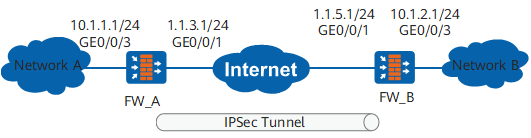
As shown in Figure 1, FW_A connects network A to the Internet and FW_B connects network B to the Internet. The networking requirements are as follows:
Network A (10.1.1.0/24) connects to GigabitEthernet 0/0/3 of FW_A.
Network B (10.1.2.0/24) connects to GigabitEthernet 0/0/3 of FW_B.
The purpose of this networking is to set up a route-based IPSec tunnel between FW_A and FW_B and to enable users on network A and network B to communicate.
Data Plan
Item |
Data |
|---|---|
FW_A |
Interface number: GigabitEthernet 0/0/3 IP address: 10.1.1.1/24 Security zone: Trust |
Interface number: GigabitEthernet 0/0/1 IP address: 1.1.3.1/24 Security zone: Untrust |
|
IPSec tunnel interface configuration Source IP: 1.1.3.1 Destination IP: 1.1.5.1 IP address: any address that does not conflict with other IP addresses |
|
IPSec profile configuration Authentication type: pre-shared key Pre-shared key: Test!1234 Local ID type: IP Peer ID type: any |
|
FW_B |
Interface number: GigabitEthernet 0/0/1 IP address: 1.1.5.1/24 Security zone: Untrust |
Interface number: GigabitEthernet 0/0/3 IP address: 10.1.2.1/24 Security zone: Trust |
|
IPSec tunnel interface configuration Source IP: 1.1.5.1 Destination IP: 1.1.3.1 IP address: any address that does not conflict with other IP addresses |
|
IPSec profile configuration Authentication type: pre-shared key Pre-shared key: Test!1234 Local ID: IP Peer ID: any |
Configuration Roadmap
The roadmap for configuring FW_A is similar to that of FW_B:
- Configure interfaces.
- Configure security policies to permit packets between specified subnets.
- Create a static route to the peer end.
- Configure IPSec tunnel interfaces and routes to these interfaces.
- Configure the IPSec profile, including basic IPSec profile information and proposal parameters for security association (SA) negotiation.
Procedure
- Perform basic configurations on FW_A, including interface IP addresses, security zones to which the interfaces are added, interzone security policies, and static routes.
- Configure interzone security policies.
Configure the security policies between the Trust and Untrust zones.
[FW_A] security-policy
[FW_A-policy-security] rule name policy1
[FW_A-policy-security-rule-policy1] source-zone trust
[FW_A-policy-security-rule-policy1] destination-zone untrust
[FW_A-policy-security-rule-policy1] source-address 10.1.1.0 24
[FW_A-policy-security-rule-policy1] destination-address 10.1.2.0 24
[FW_A-policy-security-rule-policy1] action permit
[FW_A-policy-security-rule-policy1] quit
[FW_A-policy-security] rule name policy2
[FW_A-policy-security-rule-policy2] source-zone untrust
[FW_A-policy-security-rule-policy2] destination-zone trust
[FW_A-policy-security-rule-policy2] source-address 10.1.2.0 24
[FW_A-policy-security-rule-policy2] destination-address 10.1.1.0 24
[FW_A-policy-security-rule-policy2] action permit
[FW_A-policy-security-rule-policy2] quit
Configure the security policies between the Local and Untrust zones.

The Local-Untrust interzone policy controls whether IKE negotiation packets can pass through the FW. This policy can use the source and destination addresses, protocol, or port as the matching condition. In this example, the source and destination addresses are used as the matching condition. To use the protocol or port as the matching condition, you need to enable ESP and port 500 for UDP (port 4500 also in NAT traversal scenarios).
Configure the security policies between the Local and Untrust zones to permit the interzone traffic for the negotiation between the tunnel endpoints.
[FW_A-policy-security] rule name policy3
[FW_A-policy-security-rule-policy3] source-zone local
[FW_A-policy-security-rule-policy3] destination-zone untrust
[FW_A-policy-security-rule-policy3] source-address 1.1.3.1 32
[FW_A-policy-security-rule-policy3] destination-address 1.1.5.1 32
[FW_A-policy-security-rule-policy3] action permit
[FW_A-policy-security-rule-policy3] quit
[FW_A-policy-security] rule name policy4
[FW_A-policy-security-rule-policy4] source-zone untrust
[FW_A-policy-security-rule-policy4] destination-zone local
[FW_A-policy-security-rule-policy4] source-address 1.1.5.1 32
[FW_A-policy-security-rule-policy4] destination-address 1.1.3.1 32
[FW_A-policy-security-rule-policy4] action permit
[FW_A-policy-security-rule-policy4] quit
[FW_A-policy-security] quit
- Configure interzone security policies.
- Configure IPSec on FW_A.
- Perform basic configurations on FW_B, including interface IP addresses, security zones to which the interfaces are added, interzone security policies, and static routes.
- Configure interzone security policies.
Configure the security policies between the Trust and Untrust zones.
[FW_B] security-policy
[FW_B-policy-security] rule name policy1
[FW_B-policy-security-rule-policy1] source-zone trust
[FW_B-policy-security-rule-policy1] destination-zone untrust
[FW_B-policy-security-rule-policy1] source-address 10.1.2.0 24
[FW_B-policy-security-rule-policy1] destination-address 10.1.1.0 24
[FW_B-policy-security-rule-policy1] action permit
[FW_B-policy-security-rule-policy1] quit
[FW_B-policy-security] rule name policy2
[FW_B-policy-security-rule-policy2] source-zone untrust
[FW_B-policy-security-rule-policy2] destination-zone trust
[FW_B-policy-security-rule-policy2] source-address 10.1.1.0 24
[FW_B-policy-security-rule-policy2] destination-address 10.1.2.0 24
[FW_B-policy-security-rule-policy2] action permit
[FW_B-policy-security-rule-policy2] quit
Configure the security policies between the Local and Untrust zones.
The Local-Untrust interzone policy controls whether IKE negotiation packets can pass through the FW. This policy can use the source and destination addresses, protocol, or port as the matching condition. In this example, the source and destination addresses are used as the matching condition. To use the protocol or port as the matching condition, you need to enable ESP and port 500 for UDP (port 4500 also in NAT traversal scenarios).
Configure the security policies between the Local and Untrust zones to permit the interzone traffic for the negotiation between the tunnel endpoints.
[FW_B-policy-security] rule name policy3
[FW_B-policy-security-rule-policy3] source-zone local
[FW_B-policy-security-rule-policy3] destination-zone untrust
[FW_B-policy-security-rule-policy3] source-address 1.1.5.1 32
[FW_B-policy-security-rule-policy3] destination-address 1.1.3.1 32
[FW_B-policy-security-rule-policy3] action permit
[FW_B-policy-security-rule-policy3] quit
[FW_B-policy-security] rule name policy4
[FW_B-policy-security-rule-policy4] source-zone untrust
[FW_B-policy-security-rule-policy4] destination-zone local
[FW_B-policy-security-rule-policy4] source-address 1.1.3.1 32
[FW_B-policy-security-rule-policy4] destination-address 1.1.5.1 32
[FW_B-policy-security-rule-policy4] action permit
[FW_B-policy-security-rule-policy4] quit
[FW_B-policy-security] quit
- Configure interzone security policies.
- Configure IPSec on FW_B.
Verification
After the configuration is complete, run the ping command on PC1 to trigger IKE negotiation.
If the IKE negotiation is successful, a tunnel is established and PC2 can be pinged from PC1. If the IKE negotiation fails, no tunnel is established and PC2 cannot be pinged from PC1.
Run the display ike sa and display ipsec sa commands on both FW_A and FW_B to check SA establishment.
Take FW_B for example. If the following information is displayed, the IKE SA and IPSec SA are successfully established.
<FW_B> display ike sa IKE SA information : Conn-ID Peer VPN Flag(s) Phase RemoteType RemoteID ----------------------------------------------------------------------------- 16777239 1.1.3.1:500 RD|ST|A v2:2 IP 1.1.3.1 16777232 1.1.3.1:500 RD|ST|A v2:1 IP 1.1.3.1 Number of IKE SA : 2 ------------------------------------------------------------------------------- Flag Description: RD--READY ST--STAYALIVE RL--REPLACED FD--FADING TO--TIMEOUT HRT--HEARTBEAT LKG--LAST KNOWN GOOD SEQ NO. BCK--BACKED UP M--ACTIVE S--STANDBY A--ALONE NEG--NEGOTIATING<FW_B> display ipsec sa ipsec sa information: =============================== Interface: Tunnel1 =============================== ----------------------------- IPSec profile name: "pro1" Mode : PROF-ISAKMP ----------------------------- Connection ID : 16782310 Encapsulation mode: Tunnel Tunnel local : 1.1.5.1 Tunnel remote : 1.1.3.1 [Outbound ESP SAs] SPI: 3174037361 (0xbd2ff771) Proposal: ESP-ENCRYPT-AES-256 SHA2-256-128 SA remaining key duration (kilobytes/sec): 20971520/3551 Max sent sequence-number: 1 UDP encapsulation used for NAT traversal: N SA encrypted packets (number/bytes): 0/0 [Inbound ESP SAs] SPI: 867840252 (0x33ba30fc) Proposal: ESP-ENCRYPT-AES-256 SHA2-256-128 SA remaining key duration (kilobytes/sec): 20971520/3551 Max received sequence-number: 1 UDP encapsulation used for NAT traversal: N SA decrypted packets (number/bytes): 0/0 Anti-replay : Disable
Configuration Files
-
#
 sysname FW_A
#
ipsec proposal tran1
 esp authentication-algorithm sha2-256
 esp encryption-algorithm aes-256
#
ike proposal 10
  encryption-algorithm aes-256
  dh group14
  authentication-algorithm sha2-256
  authentication-method pre-share
  integrity-algorithm hmac-sha2-256
  prf hmac-sha2-256
#
ike peer b
  pre-shared-key %@%@27a*8u}Q.Qj4JQSKM(`Gla(_%@%@
  ike-proposal 10
#
ipsec profile pro1
 ike-peer b
 proposal tran1
#
interface GigabitEthernet0/0/3
 undo shutdown
 ip address 10.1.1.1 255.255.255.0
#
interface GigabitEthernet0/0/1
 undo shutdown
 ip address 1.1.3.1 255.255.255.0
#
interface Tunnel 1
 ip address 172.16.2.1 255.255.255.0
 tunnel-protocol ipsec
 source 1.1.3.1
 destination 1.1.5.1
 ipsec profile pro1
#
firewall zone trust
 set priority 85
 add interface GigabitEthernet0/0/3
#
firewall zone untrust
 set priority 5
 add interface GigabitEthernet0/0/1
 add interface tunnel1
#
ip route-static 1.1.5.0 255.255.255.0 1.1.3.2
ip route-static 10.1.2.0 255.255.255.0 Tunnel1
#
security-policy
 rule name policy1
  source-zone trust
  destination-zone untrust
  source-address 10.1.1.0 mask 255.255.255.0
  destination-address 10.1.2.0 mask 255.255.255.0
  action permit
 rule name policy2
  source-zone untrust
  destination-zone trust
  source-address 10.1.2.0 mask 255.255.255.0
  destination-address 10.1.1.0 mask 255.255.255.0
  action permit
 rule name policy3
  source-zone local
  destination-zone untrust
  source-address 1.1.3.1 mask 255.255.255.255
  destination-address 1.1.5.1 mask 255.255.255.255
  action permit
 rule name policy4
  source-zone untrust
  destination-zone local
  source-address 1.1.5.1 mask 255.255.255.255
  destination-address 1.1.3.1 mask 255.255.255.255
  action permit
#
return
-
#
 sysname FW_B
#
ipsec proposal tran1
 esp authentication-algorithm sha2-256
 esp encryption-algorithm aes-256
#
ike proposal 10
  encryption-algorithm aes-256
  dh group14
  authentication-algorithm sha2-256
  authentication-method pre-share
  integrity-algorithm hmac-sha2-256
  prf hmac-sha2-256
#
ike peer a
 pre-shared-key %@%@R6jc8T.C"5P]om4P|dNPP}PI%@%@
 ike-proposal 10
#
ipsec profile pro1
 ike-peer a
 proposal tran1
#
interface GigabitEthernet0/0/3
 undo shutdown
 ip address 10.1.2.1 255.255.255.0
#
interface GigabitEthernet0/0/1
 undo shutdown
 ip address 1.1.5.1 255.255.255.0
#
interface Tunnel 1
 ip address 172.16.2.2 255.255.255.0
 tunnel-protocol ipsec
 source 1.1.5.1
 destination 1.1.3.1
 ipsec profile pro1
#
firewall zone trust
 set priority 85
 add interface GigabitEthernet0/0/3
#
firewall zone untrust
 set priority 5
 add interface GigabitEthernet0/0/1
 add interface tunnel1
#
ip route-static 1.1.3.0 255.255.255.0 1.1.5.2
ip route-static 10.1.1.0 255.255.255.0 Tunnel1
#
security-policy
 rule name policy1
  source-zone trust
  destination-zone untrust
  source-address 10.1.2.0 mask 255.255.255.0
  destination-address 10.1.1.0 mask 255.255.255.0
  action permit
 rule name policy2
  source-zone untrust
  destination-zone trust
  source-address 10.1.1.0 mask 255.255.255.0
  destination-address 10.1.2.0 mask 255.255.255.0
  action permit
 rule name policy3
  source-zone local
  destination-zone untrust
  source-address 1.1.5.1 mask 255.255.255.255
  destination-address 1.1.3.1 mask 255.255.255.255
  action permit
 rule name policy4
  source-zone untrust
  destination-zone local
  source-address 1.1.3.1 mask 255.255.255.255
  destination-address 1.1.5.1 mask 255.255.255.255
  action permit
#
return