CLI: Example for Configuring GRE over IPSec Between Two Gateways Using IPSec Policy
Networking Requirements
As shown in Figure 1, network A and network B connect to the Internet through FW_A and FW_B respectively. Users on network A need to access resources on network B through a GRE tunnel. The network environment is as follows:
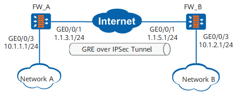
Data Plan
Item |
Data |
|---|---|
FW_A |
Interface number: GigabitEthernet 0/0/3 IP address: 10.1.1.1/24 Security zone: Trust |
Interface number: GigabitEthernet 0/0/1 IP address: 1.1.3.1/24 Security zone: Untrust |
|
GRE tunnel interface configuration Source IP address: 1.1.3.1 Destination IP address: 1.1.5.1 IP address: any address that does not conflict with other IP addresses |
|
IPSec policy configuration Authentication type: Pre-shared key Pre-shared key: Test!123 Local ID type: IP address Peer ID type: any |
|
FW_B |
Interface number: GigabitEthernet 0/0/1 IP address: 1.1.5.1/24 Security zone: Untrust |
Interface number: GigabitEthernet 0/0/3 IP address: 10.1.2.1/24 Security zone: Trust |
|
GRE tunnel interface configuration Source IP address: 1.1.5.1 Destination IP address: 1.1.3.1 IP address: any address that does not conflict with other IP addresses |
|
IPSec policy configuration Authentication type: Pre-shared key Pre-shared key: Test!123 Local ID type: IP address Peer ID type: any |
Configuration Roadmap
The configuration roadmap is as follows:
- Establish a GRE tunnel between FW_A and FW_B to implement communication between network A and network B.
- Configure IPSec to encrypt data transmitted between FW_A and FW_B.
In this example, IKE negotiation mode is used.
When GRE over IPSec is used, two ends of the GRE tunnel are the source and destination of the data flows to be protected by IPSec. Therefore, the source and destination addresses in the ACL configured on FW_A are 1.1.3.1 and 1.1.5.1 respectively.
Procedure
- Perform basic configurations on FW_A.
- Configure interzone security policies.
[FW_A] security-policy
[FW_A-policy-security] rule name policy1
[FW_A-policy-security-rule-policy1] source-zone trust
[FW_A-policy-security-rule-policy1] destination-zone untrust
[FW_A-policy-security-rule-policy1] source-address 10.1.1.0 24
[FW_A-policy-security-rule-policy1] destination-address 10.1.2.0 24
[FW_A-policy-security-rule-policy1] action permit
[FW_A-policy-security-rule-policy1] quit
[FW_A-policy-security] rule name policy2
[FW_A-policy-security-rule-policy2] source-zone untrust
[FW_A-policy-security-rule-policy2] destination-zone trust
[FW_A-policy-security-rule-policy2] source-address 10.1.2.0 24
[FW_A-policy-security-rule-policy2] destination-address 10.1.1.0 24
[FW_A-policy-security-rule-policy2] action permit
[FW_A-policy-security-rule-policy2] quit
[FW_A-policy-security] rule name policy3
[FW_A-policy-security-rule-policy3] source-zone local
[FW_A-policy-security-rule-policy3] destination-zone untrust
[FW_A-policy-security-rule-policy3] source-address 1.1.3.1 32
[FW_A-policy-security-rule-policy3] destination-address 1.1.5.1 32
[FW_A-policy-security-rule-policy3] action permit
[FW_A-policy-security-rule-policy3] quit
[FW_A-policy-security] rule name policy4
[FW_A-policy-security-rule-policy4] source-zone untrust
[FW_A-policy-security-rule-policy4] destination-zone local
[FW_A-policy-security-rule-policy4] source-address 1.1.5.1 32
[FW_A-policy-security-rule-policy4] destination-address 1.1.3.1 32
[FW_A-policy-security-rule-policy4] action permit
[FW_A-policy-security-rule-policy4] quit
[FW_A-policy-security] quit

The Local-Untrust interzone policy controls whether IKE negotiation packets can pass through the FW. This policy can use the source and destination addresses, protocol, or port as the matching condition. In this example, the source and destination addresses are used as the matching condition. To use the protocol or port as the matching condition, you need to enable ESP and port 500 for UDP (port 4500 also in NAT traversal scenarios).
- Configure interzone security policies.
- Configure GRE on FW_A.
-
[FW_A] interface tunnel 1 Set the encapsulation mode of interface Tunnel 1.
[FW_A-Tunnel1] tunnel-protocol gre- Set the IP address of interface Tunnel 1.
[FW_A-Tunnel1] ip address 30.1.1.1 24 The IP address of a tunnel interface can be specified randomly. When a dynamic routing protocol is used to generate routes passing through tunnel interfaces, the IP addresses of the tunnel interfaces at both ends of the GRE tunnel must be in the same network segment.
Set the source IP address of interface Tunnel 1, that is, IP address of GigabitEthernet 0/0/1 on FW_A.
[FW_A-Tunnel1] source 1.1.3.1Set the destination IP address of interface Tunnel 1, that is, IP address of GigabitEthernet 0/0/1 on FW_B.
[FW_A-Tunnel1] destination 1.1.5.1
[FW_A-Tunnel1] quit
Add interface Tunnel 1 to the Untrust zone.
[FW_A] firewall zone untrust
[FW_A-zone-untrust] add interface tunnel 1
[FW_A-zone-untrust] quit
-
- Configure a static route from FW_A to network B through interface Tunnel 1.
Suppose that the next hop of the route to network B from FW_A through GigabitEthernet 0/0/1 is 1.1.3.2.
[FW_A] ip route-static 10.1.2.0 255.255.255.0 tunnel 1
[FW_A] ip route-static 1.1.5.0 255.255.255.0 GigabitEthernet 0/0/1 1.1.3.2
- Configure an IPSec policy and apply the policy to the corresponding interface on FW_A.
Create advanced ACL 3000, and configure a rule for packets whose source IP address is 1.1.3.1 and destination IP address is 1.1.5.1.
[FW_A] acl 3000
[FW_A-acl-adv-3000] rule 5 permit ip source 1.1.3.1 0 destination 1.1.5.1 0
[FW_A-acl-adv-3000] quit
The source and destination IP addresses are those of interface Tunnel1.
Configure IPSec proposal tran1 using the default parameters.
[FW_A] ipsec proposal tran1
[FW_A-ipsec-proposal-tran1] esp authentication-algorithm sha2-256
[FW_A-ipsec-proposal-tran1] esp encryption-algorithm aes-256
[FW_A-ipsec-proposal-tran1] quit
Configure an IKE proposal using the default parameters.
[FW_A] ike proposal 10
[FW_A-ike-proposal-10] authentication-method pre-share
[FW_A-ike-proposal-10] prf hmac-sha2-256
[FW_A-ike-proposal-10] encryption-algorithm aes-256
[FW_A-ike-proposal-10] dh group14
[FW_A-ike-proposal-10] integrity-algorithm hmac-sha2-256
[FW_A-ike-proposal-10] quit
-
[FW_A] ike peer b
[FW_A-ike-peer-b] ike-proposal 10
[FW_A-ike-peer-b] remote-address 1.1.5.1
[FW_A-ike-peer-b] pre-shared-key Test!123
[FW_A-ike-peer-b] quit
Configure an IPSec policy using the IKE negotiation mode.
[FW_A] ipsec policy map1 10 isakmp
[FW_A-ipsec-policy-isakmp-map1-10] security acl 3000
[FW_A-ipsec-policy-isakmp-map1-10] proposal tran1
[FW_A-ipsec-policy-isakmp-map1-10] ike-peer b
[FW_A-ipsec-policy-isakmp-map1-10] quit
Apply IPSec policy map1 to GigabitEthernet 0/0/1.
[FW_A] interface GigabitEthernet 0/0/1
[FW_A-GigabitEthernet0/0/1] ipsec policy map1
[FW_A-GigabitEthernet0/0/1] quit
- Set basic parameters on FW_B.
- Configure interzone security policies.
[FW_B] security-policy
[FW_B-policy-security] rule name policy1
[FW_B-policy-security-rule-policy1] source-zone trust
[FW_B-policy-security-rule-policy1] destination-zone untrust
[FW_B-policy-security-rule-policy1] source-address 10.1.2.0 24
[FW_B-policy-security-rule-policy1] destination-address 10.1.1.0 24
[FW_B-policy-security-rule-policy1] action permit
[FW_B-policy-security-rule-policy1] quit
[FW_B-policy-security] rule name policy2
[FW_B-policy-security-rule-policy2] source-zone untrust
[FW_B-policy-security-rule-policy2] destination-zone trust
[FW_B-policy-security-rule-policy2] source-address 10.1.1.0 24
[FW_B-policy-security-rule-policy2] destination-address 10.1.2.0 24
[FW_B-policy-security-rule-policy2] action permit
[FW_B-policy-security-rule-policy2] quit
[FW_B-policy-security] rule name policy3
[FW_B-policy-security-rule-policy3] source-zone local
[FW_B-policy-security-rule-policy3] destination-zone untrust
[FW_B-policy-security-rule-policy3] source-address 1.1.5.1 32
[FW_B-policy-security-rule-policy3] destination-address 1.1.3.1 32
[FW_B-policy-security-rule-policy3] action permit
[FW_B-policy-security-rule-policy3] quit
[FW_B-policy-security] rule name policy4
[FW_B-policy-security-rule-policy4] source-zone untrust
[FW_B-policy-security-rule-policy4] destination-zone local
[FW_B-policy-security-rule-policy4] source-address 1.1.3.1 32
[FW_B-policy-security-rule-policy4] destination-address 1.1.5.1 32
[FW_B-policy-security-rule-policy4] action permit
[FW_B-policy-security-rule-policy4] quit
[FW_B-policy-security] quit
The Local-Untrust interzone policy controls whether IKE negotiation packets can pass through the FW. This policy can use the source and destination addresses, protocol, or port as the matching condition. In this example, the source and destination addresses are used as the matching condition. To use the protocol or port as the matching condition, you need to enable ESP and port 500 for UDP (port 4500 also in NAT traversal scenarios).
- Configure interzone security policies.
- Configure GRE on FW_B.
-
[FW_B] interface tunnel 1 Set the encapsulation mode of interface Tunnel 1.
[FW_B-Tunnel1] tunnel-protocol greSet the IP address of interface Tunnel 1.
[FW_B-Tunnel1] ip address 30.1.1.2 24Set the source IP address of interface Tunnel 1, that is, IP address of GigabitEthernet 0/0/1 on FW_B.
[FW_B-Tunnel1] source 1.1.5.1- Set the destination IP address of interface Tunnel 1, that is, IP address of GigabitEthernet 0/0/1 on FW_A.
[FW_B-Tunnel1] destination 1.1.3.1
[FW_B-Tunnel1] quit
- Add interface Tunnel 1 to the Untrust zone.
[FW_B] firewall zone untrust
[FW_B-zone-untrust] add interface tunnel 1
[FW_B-zone-untrust] quit
-
- Configure a static route from FW_B to network A through interface Tunnel 1.
Suppose that the next hop of the route from FW_B to network A through GigabitEthernet 0/0/1 is 1.1.5.2.
[FW_B] ip route-static 10.1.1.0 255.255.255.0 tunnel 1
[FW_B] ip route-static 1.1.3.0 255.255.255.0 GigabitEthernet0/0/1 1.1.5.2
- Configure an IPSec policy and apply the policy to the corresponding interface on FW_B.
Create advanced ACL 3000, and configure a rule for packets whose source IP address is 1.1.5.1 and destination IP address is 1.1.3.1.
[FW_B] acl 3000
[FW_B-acl-adv-3000] rule 5 permit ip source 1.1.5.1 0 destination 1.1.3.1 0
[FW_B-acl-adv-3000] quit
- Configure IPSec proposal tran1 using the default parameters.
[FW_B] ipsec proposal tran1
[FW_B-ipsec-proposal-tran1] esp authentication-algorithm sha2-256
[FW_B-ipsec-proposal-tran1] esp encryption-algorithm aes-256
[FW_B-ipsec-proposal-tran1] quit
- Configure an IKE proposal using the default parameters.
[FW_B] ike proposal 10
[FW_B-ike-proposal-10] authentication-method pre-share
[FW_B-ike-proposal-10] prf hmac-sha2-256
[FW_B-ike-proposal-10] encryption-algorithm aes-256
[FW_B-ike-proposal-10] dh group14
[FW_B-ike-proposal-10] integrity-algorithm hmac-sha2-256
[FW_B-ike-proposal-10] quit
- Configure an IKE peer.
[FW_B] ike peer a
[FW_B-ike-peer-a] ike-proposal 10
[FW_B-ike-peer-a] remote-address 1.1.3.1
[FW_B-ike-peer-a] pre-shared-key Test!123
[FW_B-ike-peer-a] quit
- Configure an IPSec policy.
[FW_B] ipsec policy map1 10 isakmp
[FW_B-ipsec-policy-isakmp-map1-10] security acl 3000
[FW_B-ipsec-policy-isakmp-map1-10] proposal tran1
[FW_B-ipsec-policy-isakmp-map1-10] ike-peer a
[FW_B-ipsec-policy-isakmp-map1-10] quit
- Apply IPSec policy map1 to GigabitEthernet 0/0/1.
[FW_B] interface GigabitEthernet 0/0/1
[FW_B-GigabitEthernet0/0/1] ipsec policy map1
[FW_B-GigabitEthernet0/0/1] quit
Configuration Files
-
#
 sysname FW_A
#
acl number 3000
 rule 5 permit ip source 1.1.3.1 0 destination 1.1.5.1 0
#
ipsec proposal tran1
 esp authentication-algorithm sha2-256
 esp encryption-algorithm aes-256
#
ike proposal 10
  encryption-algorithm aes-256
  dh group14
  authentication-algorithm sha2-256
  authentication-method pre-share
  integrity-algorithm hmac-sha2-256
  prf hmac-sha2-256
#
ike peer b
  pre-shared-key %^%#o3Z7,b[Ox7Sc#r-f+WDC:D=s%^%#
  ike-proposal 10
  remote-address 1.1.5.1
#
ipsec policy map1 10 isakmp
 security acl 3000
 ike-peer b
 proposal tran1
#
interface GigabitEthernet0/0/3
 undo shutdown
 ip address 10.1.1.1 255.255.255.0
#
interface GigabitEthernet0/0/1
 undo shutdown
 ip address 1.1.3.1 255.255.255.0
 ipsec policy map1
#
interface Tunnel1
 ip address 30.1.1.1 255.255.255.0
 tunnel-protocol gre
 source 1.1.3.1
 destination 1.1.5.1
#
firewall zone trust
 set priority 85
 add interface GigabitEthernet0/0/3
#
firewall zone untrust
 set priority 5
 add interface GigabitEthernet0/0/1
 add interface tunnel 1
#
 ip route-static 10.1.2.0 255.255.255.0 tunnel 1
 ip route-static 1.1.5.0 255.255.255.0 GigabitEthernet0/0/1 1.1.3.2
#
security-policy
  rule name policy1
    source-zone trust
    destination-zone untrust
    source-address 10.1.1.0 mask 255.255.255.0
    destination-address 10.1.2.0 mask 255.255.255.0
    action permit
  rule name policy2
    source-zone untrust
    destination-zone trust
    source-address 10.1.2.0 mask 255.255.255.0
    destination-address 10.1.1.0 mask 255.255.255.0
    action permit
  rule name policy3
    source-zone local
    destination-zone untrust
    source-address 1.1.3.1 mask 255.255.255.255
    destination-address 1.1.5.1 mask 255.255.255.255
    action permit
  rule name policy4
    source-zone untrust
    destination-zone local
    source-address 1.1.5.1 mask 255.255.255.255
    destination-address 1.1.3.1 mask 255.255.255.255
    action permit
#
return
-
#
 sysname FW_B
#
acl number 3000
 rule 5 permit ip source 1.1.5.1 0 destination 1.1.3.1 0
#
ipsec proposal tran1
 esp authentication-algorithm sha2-256
 esp encryption-algorithm aes-256
#
ike proposal 10
  encryption-algorithm aes-256
  dh group14
  authentication-algorithm sha2-256
  authentication-method pre-share
  integrity-algorithm hmac-sha2-256
  prf hmac-sha2-256
#
ike peer a
 pre-shared-key %^%#2@@y~:)7dX56AoVG1S@&0)Xf%^%#
 ike-proposal 10
 remote-address 1.1.3.1
#
ipsec policy map1 10 isakmp
 security acl 3000
 ike-peer a
 proposal tran1
#
interface GigabitEthernet0/0/3
 undo shutdown
 ip address 10.1.2.1 255.255.255.0
#
interface GigabitEthernet0/0/1
 undo shutdown
 ip address 1.1.5.1 255.255.255.0
 ipsec policy map1
#
interface Tunnel1
 ip address 30.1.1.2 255.255.255.0
 tunnel-protocol gre
 source 1.1.5.1
 destination 1.1.3.1
#
firewall zone trust
 set priority 85
 add interface GigabitEthernet0/0/3
#
firewall zone untrust
 set priority 5
 add interface GigabitEthernet0/0/1
 add interface tunnel 1
#
 ip route-static 10.1.1.0 255.255.255.0 tunnel 1
 ip route-static 1.1.3.0 255.255.255.0 GigabitEthernet0/0/1 1.1.5.2
#
security-policy
  rule name policy1
    source-zone trust
    destination-zone untrust
    source-address 10.1.2.0 mask 255.255.255.0
    destination-address 10.1.1.0 mask 255.255.255.0
    action permit
  rule name policy2
    source-zone untrust
    destination-zone trust
    source-address 10.1.1.0 mask 255.255.255.0
    destination-address 10.1.2.0 mask 255.255.255.0
    action permit
  rule name policy3
    source-zone local
    destination-zone untrust
    source-address 1.1.5.1 mask 255.255.255.255
    destination-address 1.1.3.1 mask 255.255.255.255
    action permit
  rule name policy4
    source-zone untrust
    destination-zone local
    source-address 1.1.3.1 mask 255.255.255.255
    destination-address 1.1.5.1 mask 255.255.255.255
    action permit
#
return