Configuring a Layer-3 Ethernet Subinterface
This section describes how to configure a Layer-3 Ethernet subinterface.
Context
Subinterfaces are logical or virtual interfaces created on a physical interface. Subinterfaces share the physical parameters of the physical interface on which they are created. However, subinterfaces have their own data link layer and network layer parameters. A subinterface status change does not affect the main interface status, whereas a main interface status change affects the subinterface status. Subinterfaces work properly only when their main interface is in the Up state.
Subinterfaces can be created on Layer-3 Ethernet and Eth-Trunk interfaces. To distinguish VLAN packets on a Layer-3 Ethernet interface or an Eth-Trunk interface, configure subinterfaces with different VLAN IDs. Each subinterface with a specific VLAN ID forwards packets carrying the VLAN ID, which provides configuration flexibility.
Procedure
- Choose .
- Click Add.
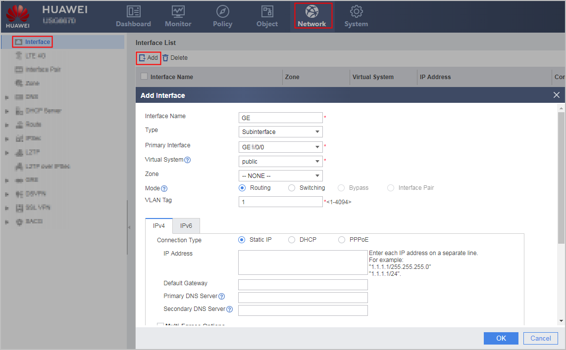
- Set the following subinterface parameters.
Parameter
Description
Interface Name
Alias name for a subinterface.
Type
Type of a subinterface to be created.
When creating a subinterface, set this parameter to Subinterface.
Primary Interface
Type and number of a Layer-3 interface to which the new subinterface belongs.
Virtual System
Name of a virtual system for a subinterface.
The virtual system must exist on the device.
Zone
Security zone to which a subinterface is to be added.
You can directly add a subinterface to an existing security zone. However, if the desired security zone does not exist, create one and then add the interface to it. For details, see Security Zones.
Mode
Working mode of the subinterface which works at Layer-3: Route.
VLAN Tag
ID of a VLAN to which a subinterface belongs. Traffic on subinterfaces of a physical interface is distinguished by VLANs.
IPv4
Connection Type
Method for a subinterface to obtain an IPv4 address.
- Static IP: allows an administrator to specify an IPv4 address for the interface. For static IP address parameter descriptions, see Table 1.
- DHCP: uses DHCP to automatically obtain an IPv4 address.
- PPPoE: uses PPP negotiation to obtain an IPv4 address. For PPPoE parameter descriptions, see Table 2.NOTE:
When the device functions as a PPPoE client (dual-stack access), the configuration of the PPPoE user will be modified accordingly because dual-stack configuration delivery requires the same user.
Multi-Egress Options
After you select Multi-Egress Options, the interface will function as an intelligent uplink selection member interface. For details on intelligent uplink selection, see Intelligent Uplink Selection.
Carrier
Select the name of the ISP directly connected to the interface.
Selecting the ISP of the interface equals to binding an interface to an ISP interface group.
Default Route
After you select this option, the FW will generate a default route in its routing table.A default route is a special static route. When the destination address of a data packet does not match any routing table of the FW, the FW will use the default route to forward the data packet. Both the destination network address and the subnet mask of the default route are 0.0.0.0.If the interface serves as an intranet interface and has the sticky load balancing function enabled, the default route must be canceled. Otherwise, the interface cannot access extranets. By default, this function is enabled.
Carrier Route
After you enable the ISP route function, the FW will generate static routes in a batch to the ISP network. In the generated static routes, the destination is an IP address in the ISP address file, and the next hop is the gateway address specified on the outbound interface. These static routes are called ISP routes. They have the same priority as common static routes, and the default priority is 60.
Choose . You can view the generated ISP route entries.
Sticky load balancing
In the multi-ISP load balancing NAT server scenario, the FW looks up the routing table for an outgoing interface to send the return traffic from a server. As a result, the return traffic from the server may take a path on ISP2, although the request to the server takes a link on ISP1. The inconsistent forward and return paths may slow down or even interrupt services. To resolve this issue, configure the sticky load balancing function on the incoming interface of ISP1.The FW uses the incoming interface of the forward packets as the outgoing interface of return packets instead of looking up the routing table.NOTE:When enabling sticky load balancing on an Ethernet interface and its sub-interfaces, an Eth-Trunk interface and its sub-interfaces, a VLANIF interface, or a VXLAN interface, you must also specify the next hop. You do not need to specify the next hop on the dialer interface and tunnel interface.
The priority of direct routes is higher than that of the sticky load balancing function. The device preferentially forwards response packets based on direct routes even if the sticky load balancing function is configured.
If equal-cost multipath (ECMP) routes are configured, the sticky load balancing function is enabled by default. In case of non-equal-cost routes, the sticky load balancing function is disabled by default, and you need to enable the function.
Health Check
Apply the health check to the interface.
IPv6
IPv6
Enable the IPv6 capability.
Enabling the IPv6 capability is the prerequisite for using IPv6 functions. Choose and enable IPv6 globally to allow the FW to forward IPv6 packets.
Connection Type
Method for a subinterface to obtain an IPv6 address.
- Static IP: manually specifies an IPv6 address for the interface. For static IP address parameter descriptions, see Table 3.
- PPPoE: uses PPP negotiation to obtain an IPv6 address. For PPPoE parameter descriptions, see Table 4.NOTE:
When the device functions as a PPPoE client (dual-stack access), the configuration of the PPPoE user will be modified accordingly because dual-stack configuration delivery requires the same user.
- ND-RA: uses ND-RA to obtain an IPv6 address.
Static Neighbor
Static neighbor address for a subinterface.
This setting allows a neighbor relationship to be established and enables a device to resolve the neighbor IPv6 address into a data link layer address.
Multi-Egress Options
After selecting Multi-Egress Options, you can enable Sticky load balancing.
Sticky load balancing
In the multi-ISP load balancing scenario, the FW looks up the routing table for an outgoing interface to send the return traffic from a server. As a result, the return traffic from the server may take a path on ISP2, although the request to the server takes a link on ISP1. The inconsistent forward and return paths may slow down or even interrupt services. To resolve this issue, configure the sticky load balancing function on the incoming interface of ISP1. The FW uses the incoming interface of the forward packets as the outgoing interface of return packets instead of looking up the routing table.NOTE:When enabling sticky load balancing on an Ethernet interface and its sub-interfaces, an Eth-Trunk interface and its sub-interfaces, a VLANIF interface, or a VXLAN interface, you must also specify the next hop. You do not need to specify the next hop on the dialer interface and tunnel interface.
The priority of direct routes is higher than that of the sticky load balancing function. The device preferentially forwards response packets based on direct routes even if the sticky load balancing function is configured.
If equal-cost multipath (ECMP) routes are configured, the sticky load balancing function is enabled by default. In case of non-equal-cost routes, the sticky load balancing function is disabled by default, and you need to enable the function.
Interface Bandwidth
Ingress Bandwidth
Maximum bandwidth for inbound traffic on the interface.
Egress Bandwidth
Maximum bandwidth for outbound traffic on the interface.
Overload Protection Threshold
Bandwidth usage of the link.
After you select Multi-Egress Options, you can set overload protection thresholds for the inbound and Egress Bandwidths of the interface. If an interface is overloaded, the interface no longer participates in intelligent uplink selection.
Access Management
Access Management
This function allows an administrator to access a FW using HTTP, HTTPS, ping, SSH, SNMP, NETCONF, or Telnet. Interface access control takes precedence over security policies. This means that an administrator can use an access control-enabled interface to access a FW even if no security policy is configured for communication between the zone of the interface and a local zone.
This parameter can only be set when Mode is set to Route.HTTP: allows an administrator to use the web browser (HTTP) to access a device through a VLAN interface. If HTTP is not selected, the interface discards HTTP packets after receiving them. This parameter takes effect only after the HTTP service is enabled.
HTTPS: allows an administrator to use the web browser (HTTPS) to access a device through a VLAN interface. If HTTPS is not selected, the interface discards HTTPS packets after receiving them. This parameter takes effect only after the HTTPS service is enabled.
- Ping: allows an interface to respond to ping requests. A ping checks interface connectivity. If Ping is not selected, the ping function is disabled.
- SSH: allows an administrator to use SSH to access a device. If SSH is not selected, the interface discards SSH packets after receiving them.
Telnet: allows an administrator to use Telnet to access a device. If Telnet is not selected, the interface discards them after receiving them.
- SNMP: allows administrators to use an SNMP NMS to access a device. If SNMP is not selected, the interface discards SNMP packets after receiving them.
NETCONF: allows an administrator to use NETCONF NMS to access a device. If NETCONF is not selected, the interface discards NETCONF packets after receiving them.
By default, the management interface (GigabitEthernet 0/0/0) allows HTTP, HTTPS, ping. access to a FW, and a non-management interface denies HTTP, HTTPS, ping, SSH, SNMP, NETCONF, or Telnet. access to a FW.
Advanced
IPv4 MTU
IPv6 MTU
Maximum transmission unit of the interface. After the MTU of an interface is modified, you need to restart the interface to validate the MTU.
This parameter can only be set when Mode is set to Route.
Strict ARP Learning
Enable the strict Address Resolution Protocol (ARP) learning.
Table 1 Static IPv4 address parameters Parameter
Description
IP Address
IPv4 address of a subinterface.
The IPv4 address must be unique on a network.
Default Gateway
IP address of the default gateway of a subinterface.
The default gateway must be on the same network segment as the IPv4 address of the subinterface.
This setting allows the device to generate a default IPv4 route, in which the current subinterface functions as an outbound interface, and the default gateway functions as a next hop.
Preferred DNS server
IP address of the preferred DNS server.
The configurations completed here will be automatically synchronized to Transparent DNS Proxy in .
NOTE:The DNS server bound to an interface is used only in DNS transparent proxy. You must set a global DNS server for the device to access domain names.
Alternate DNS server
IP address of the alternate DNS server.
The configurations completed here will be automatically synchronized to Transparent DNS Proxy in .
NOTE:The DNS server bound to an interface is used only in DNS transparent proxy. You must set a global DNS server for the device to access domain names.
Table 2 IPv4 PPPoE parameters Parameter
Description
User Name
User name for PPPoE dial-up.
The user name is provided by an ISP.
Password
Password for PPPoE dial-up.
The password is provided by an ISP.
Online Mode
PPPoE dial-up mode:
- Always Online: A device automatically attempts to dial up to a peer end once a physical link connected to the peer end is Up. If the dial-up connection attempt fails, the device automatically re-attempts to dial up at specified intervals. Automatic dial-up applies when the traffic volume and online duration are not restricted, such as with the yearly-payment service.
Automatic disconnection after an idle period: A device sets up a link only when there is data to be transmitted. If an established PPPoE link has no traffic to transmit and the specific link idle period elapses, the device disconnects the PPPoE link. This dial-up mode applies when the traffic volume and online duration are set, such as with the payment-by-traffic service. The payment-by-traffic service allows a specified amount of traffic to be transmitted within a specified period.
If you select Automatic disconnection after an idle period, you must also specify a link idle period.
Obtain an IP Address Automatically
Obtain an IPv4 address that a PPPoE server assigns after negotiating with a PPPoE client on a PPP link. The IPv4 address to be assigned must be specified on the PPPoE server.
Use the Following IP Address
Set an IPv4 address statically. This method requires the input of a fixed IPv4 address in IP Address. The IPv4 address to be entered is the one that a PPPoE server can assign.
Table 3 Static IPv6 address parameters Parameter
Description
IPv6 Address
IPv6 address of a subinterface.
The IPv6 address must be unique on a network.
Advertising RA Messages
Enable a device to periodically advertise RA messages, which contain the prefix option and flag bits, to announce the existence of the device.
Table 4 IPv6 PPPoE parameters Parameter
Description
User Name
User name for PPPoE dial-up.
The user name is provided by an ISP.
Password
Password for PPPoE dial-up.
The password is provided by an ISP.
Online Mode
PPPoE dial-up mode:
- Always Online: A device automatically attempts to dial up to a peer end once a physical link connected to the peer end is Up. If the dial-up connection attempt fails, the device automatically re-attempts to dial up at specified intervals. Automatic dial-up applies when the traffic volume and online duration are not restricted, such as with the yearly-payment service.
Automatic disconnection after an idle period: A device sets up a link only when there is data to be transmitted. If an established PPPoE link has no traffic to transmit and the specific link idle period elapses, the device disconnects the PPPoE link. This dial-up mode applies when the traffic volume and online duration are set, such as with the payment-by-traffic service. The payment-by-traffic service allows a specified amount of traffic to be transmitted within a specified period.
If you select Automatic disconnection after an idle period, you must also specify a link idle period.
- Click OK.
If the operation is successful, the new subinterface is displayed among Layer-3 interfaces in Interface List.
Repeat previous steps to create other subinterfaces.
Follow-up Procedure
Check the subinterface status.
- Choose .
Verify that the physical, IPv4, and IPv6 statuses of the subinterface are Up.
Enable or disable the interface.
- Choose .
- Perform either of the following operations as needed:
- To enable the interface, select the Enable check box.
- To disable the interface, clear the Enable check box.