CLI: Example for Configuring IPSec Multi-link Load Balancing
This section provides an example for configuring load balancing between two links for IPSec services.
Networking Requirements
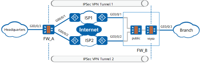
As shown in Figure 1, the egress gateway FW_A on the enterprise headquarters and the egress gateway FW_B of the remote branch network have two links. FW_A and FW_B are reachable to each other. The two gateways are connected to different carrier networks through the two links and establish two IPSec VPN tunnels. The two IPSec VPN tunnels protect the same service flows and implement load balancing for IPSec services.

- All models except USG6635E/6655E, USG6680E and USG6712E/6716E support this function.
- This example applies only to devices equipped with a single CPU and does not apply to those with multiple CPUs. (If two IPSec tunnels are distributed on different CPUs, sessions are separated.) For devices with multiple CPUs, you are advised to use hot standby load balancing. For detailed configurations, see CLI: Example for Configuring IPSec Gateway Load Balancing With Routers Connected in the Upstream and Downstream.
Data Planning
Item |
Data |
|
|---|---|---|
FW_A |
Interface: GE0/0/1 IP address: 1.1.1.1/24 Security zone where the interface resides: Untrust |
|
Interface: GE0/0/2 IP address: 2.2.2.2/24 Security zone where the interface resides: Untrust |
||
Interface: GE0/0/3 IP address: 10.1.1.1/24 Security zone where the interface resides: Trust |
||
IPSec configuration policy1 Authentication mode: pre-shared key authentication Pre-shared key: Admin@123 policy2 Authentication mode: pre-shared key authentication Pre-shared key: Admin@123 |
||
FW_B |
public |
Interface: GE0/0/1 IP address: 3.3.3.3/24 Security zone where the interface resides: Untrust |
Interface: GE0/0/2 IP address: 4.4.4.4/24 Security zone where the interface resides: Untrust |
||
Interface: Virtual-if0 IP address: 55.55.55.55/32 Security zone where the interface resides: Trust |
||
IPSec configuration ipsec1 Peer IP address: 1.1.1.1 Authentication mode: pre-shared key authentication Pre-shared key: Admin@123 ipsec2 Peer IP address: 2.2.2.2 Authentication mode: pre-shared key authentication Pre-shared key: Admin@123 |
||
vsysa |
Interface: GE0/0/3 IP address: 10.2.1.1/24 Security zone where the interface resides: Trust |
|
Interface: Virtual-if1 IP address: 56.56.56.56/32 Security zone where the interface resides: Trust |
||
Procedure
- Configure FW_A.
- Configure security policies.
- Configure the Trust-Untrust interzone policy to allow the unencapsulated and decapsulated packets through FW_A.
[FW_A] security-policy
[FW_A-policy-security] rule name 1
[FW_A-policy-security-rule-1] source-zone trust
[FW_A-policy-security-rule-1] destination-zone untrust
[FW_A-policy-security-rule-1] source-address 10.1.1.0 24
[FW_A-policy-security-rule-1] destination-address 10.2.1.0 24
[FW_A-policy-security-rule-1] action permit
[FW_A-policy-security-rule-1] quit
[FW_A-policy-security] rule name 2
[FW_A-policy-security-rule-2] source-zone untrust
[FW_A-policy-security-rule-2] destination-zone trust
[FW_A-policy-security-rule-2] source-address 10.2.1.0 24
[FW_A-policy-security-rule-2] destination-address 10.1.1.0 24
[FW_A-policy-security-rule-2] action permit
[FW_A-policy-security-rule-2] quit
- Configure the Local-Untrust interzone policy to allow IKE negotiation packets through FW_A.
The local-untrust interzone policy controls whether IKE negotiation packets can pass through the FW. This policy can use the source and destination addresses, protocol, or port as the matching condition. In this example, the source and destination addresses are used as the matching condition. To use the protocol or port as the matching condition, you need to enable ESP and port 500 for UDP (port 4500 also in NAT traversal scenarios).
[FW_A-policy-security] rule name 3
[FW_A-policy-security-rule-3] source-zone local
[FW_A-policy-security-rule-3] destination-zone untrust
[FW_A-policy-security-rule-3] source-address 1.1.1.1 32
[FW_A-policy-security-rule-3] destination-address 3.3.3.3 32
[FW_A-policy-security-rule-3] action permit
[FW_A-policy-security-rule-3] quit
[FW_A-policy-security] rule name 4
[FW_A-policy-security-rule-4] source-zone untrust
[FW_A-policy-security-rule-4] destination-zone local
[FW_A-policy-security-rule-4] source-address 3.3.3.3 32
[FW_A-policy-security-rule-4] destination-address 1.1.1.1 32
[FW_A-policy-security-rule-4] action permit
[FW_A-policy-security-rule-4] quit
[FW_A-policy-security] rule name 5
[FW_A-policy-security-rule-5] source-zone local
[FW_A-policy-security-rule-5] destination-zone untrust
[FW_A-policy-security-rule-5] source-address 2.2.2.2 32
[FW_A-policy-security-rule-5] destination-address 4.4.4.4 32
[FW_A-policy-security-rule-5] action permit
[FW_A-policy-security-rule-5] quit
[FW_A-policy-security] rule name 6
[FW_A-policy-security-rule-6] source-zone untrust
[FW_A-policy-security-rule-6] destination-zone local
[FW_A-policy-security-rule-6] source-address 4.4.4.4 32
[FW_A-policy-security-rule-6] destination-address 2.2.2.2 32
[FW_A-policy-security-rule-6] action permit
[FW_A-policy-security-rule-6] quit
[FW_A-policy-security] quit
- Configure the Trust-Untrust interzone policy to allow the unencapsulated and decapsulated packets through FW_A.
- Configure IPsec.
- Define data flows to be protected.
[FW_A] acl 3000
[FW_A-acl-adv-3000] rule 5 permit ip source 10.1.1.0 0.0.0.255 destination 10.2.1.0 0.0.0.255
[FW_A-acl-adv-3000] quit
[FW_A] acl 3001
[FW_A-acl-adv-3001] rule 5 permit ip source 10.1.1.0 0.0.0.255 destination 10.2.1.0 0.0.0.255
[FW_A-acl-adv-3001] quit
- Configure IPSec proposals.
[FW_A] ipsec proposal 1
[FW_A-ipsec-proposal-1] encapsulation-mode auto
[FW_A-ipsec-proposal-1] esp authentication-algorithm sha2-256
[FW_A-ipsec-proposal-1] esp encryption-algorithm aes-256
[FW_A-ipsec-proposal-1] quit
[FW_A] ipsec proposal 2
[FW_A-ipsec-proposal-2] encapsulation-mode auto
[FW_A-ipsec-proposal-2] esp authentication-algorithm sha2-256
[FW_A-ipsec-proposal-2] esp encryption-algorithm aes-256
[FW_A-ipsec-proposal-2] quit
- Configure Internet Key Exchange (IKE) proposals.
[FW_A] ike proposal 1
[FW_A-ike-proposal-1] authentication-method pre-share
[FW_A-ike-proposal-1] encryption-algorithm aes-256
[FW_A-ike-proposal-1] authentication-algorithm sha2-256
[FW_A-ike-proposal-1] integrity-algorithm hmac-sha2-256
[FW_A-ike-proposal-1] dh group2
[FW_A-ike-proposal-1] quit
[FW_A] ike proposal 2
[FW_A-ike-proposal-2] authentication-method pre-share
[FW_A-ike-proposal-2] encryption-algorithm aes-256
[FW_A-ike-proposal-2] authentication-algorithm sha2-256
[FW_A-ike-proposal-2] integrity-algorithm hmac-sha2-256
[FW_A-ike-proposal-2] dh group2
[FW_A-ike-proposal-2] quit
- Configure IKE peers.
By default, both IKEv1 and IKEv2 are enabled on the FW, and IKEv2 takes precedence over IKEv1. If the remote device does not support IKEv2, disable IKEv2 on the local device and use IKEv1 to perform the IKE negotiation.
[FW_A] ike peer a
[FW_A-ike-peer-a] exchange-mode auto
[FW_A-ike-peer-a] ike-proposal 1
[FW_A-ike-peer-a] pre-shared-key Admin@123
[FW_A-ike-peer-a] quit
[FW_A] ike peer b
[FW_A-ike-peer-b] exchange-mode auto
[FW_A-ike-peer-b] ike-proposal 2
[FW_A-ike-peer-b] pre-shared-key Admin@123
[FW_A-ike-peer-b] quit
- Configure an IPSec policy template.
[FW_A] ipsec policy-template template1 1
[FW_A-ipsec-policy-template-template1-1] security acl 3000
[FW_A-ipsec-policy-template-template1-1] ike-peer a
[FW_A-ipsec-policy-template-template1-1] proposal 1
[FW_A-ipsec-policy-template-template1-1] route inject dynamic
[FW_A-ipsec-policy-template-template1-1] quit
[FW_A] ipsec policy-template template2 1
[FW_A-ipsec-policy-template-template2-1] security acl 3001
[FW_A-ipsec-policy-template-template2-1] ike-peer b
[FW_A-ipsec-policy-template-template2-1] proposal 2
[FW_A-ipsec-policy-template-template2-1] route inject dynamic
[FW_A-ipsec-policy-template-template2-1] quit
In this case, Reverse Route Injection (RRI) is configured. FW_A automatically injects two UNR equal-cost routes. Then sticky load balancing is enabled by default.
- Configure a template IPSec policy.
[FW_A] ipsec policy policy1 10000 isakmp template template1
[FW_A] ipsec policy policy2 10000 isakmp template template2
- Apply the IPSec policy group on interfaces.
[FW_A] interface GigabitEthernet 0/0/1
[FW_A-GigabitEthernet0/0/1] ipsec policy policy1
[FW_A-GigabitEthernet0/0/1] quit
[FW_A] interface GigabitEthernet 0/0/2
[FW_A-GigabitEthernet0/0/2] ipsec policy policy2
[FW_A-GigabitEthernet0/0/2] quit
- Define data flows to be protected.
- Configure security policies.
- Configure FW_B.
- Configure a security policy on the root system.
- Configure a Trust-Untrust interzone policy to allow intranet users to access the Internet.
Virtual system administrators can configure strict security policies based on the IP addresses of intranet users. Therefore, the root system administrator does not need to specify the IP address range.
[FW_B] security-policy
[FW_B-policy-security] rule name to_internet
[FW_B-policy-security-rule-to_internet] source-zone trust
[FW_B-policy-security-rule-to_internet] destination-zone untrust
[FW_B-policy-security-rule-to_internet] action permit
[FW_B-policy-security-rule-to_internet] quit
- Configure the Local-Untrust interzone policy to allow IKE negotiation packets through FW_B.
The local-untrust interzone policy controls whether IKE negotiation packets can pass through the FW. This policy can use the source and destination addresses, protocol, or port as the matching condition. In this example, the source and destination addresses are used as the matching condition. To use the protocol or port as the matching condition, you need to enable ESP and port 500 for UDP (port 4500 also in NAT traversal scenarios).
[FW_B-policy-security] rule name 1
[FW_B-policy-security-rule-1] source-zone local
[FW_B-policy-security-rule-1] destination-zone untrust
[FW_B-policy-security-rule-1] source-address 3.3.3.3 32
[FW_B-policy-security-rule-1] destination-address 1.1.1.1 32
[FW_B-policy-security-rule-1] action permit
[FW_B-policy-security-rule-1] quit
[FW_B-policy-security] rule name 2
[FW_B-policy-security-rule-2] source-zone untrust
[FW_B-policy-security-rule-2] destination-zone local
[FW_B-policy-security-rule-2] source-address 1.1.1.1 32
[FW_B-policy-security-rule-2] destination-address 3.3.3.3 32
[FW_B-policy-security-rule-2] action permit
[FW_B-policy-security-rule-2] quit
[FW_B-policy-security] rule name 3
[FW_B-policy-security-rule-3] source-zone local
[FW_B-policy-security-rule-3] destination-zone untrust
[FW_B-policy-security-rule-3] source-address 4.4.4.4 32
[FW_B-policy-security-rule-3] destination-address 2.2.2.2 32
[FW_B-policy-security-rule-3] action permit
[FW_B-policy-security-rule-3] quit
[FW_B-policy-security] rule name 4
[FW_B-policy-security-rule-4] source-zone untrust
[FW_B-policy-security-rule-4] destination-zone local
[FW_B-policy-security-rule-4] source-address 2.2.2.2 32
[FW_B-policy-security-rule-4] destination-address 4.4.4.4 32
[FW_B-policy-security-rule-4] action permit
[FW_B-policy-security-rule-4] quit
[FW_B-policy-security] quit
- Configure a Trust-Untrust interzone policy to allow intranet users to access the Internet.
- Configure a security policy on the root system.
Verification
Run the display ike sa command on FW_A to check IKE SAs.
<FW_A> display ike sa
 IKE SA information :
   Conn-ID    Peer                  VPN                            Flag(s)               Phase
  ----------------------------------------------------------------------------------------------
   67108932   4.4.4.4:500                                          RD|ST|A               v2:2
   67108926   4.4.4.4:500                                          RD|ST|A               v2:1
   80         3.3.3.3:500                                          RD|A                  v2:1
   79         3.3.3.3:500                                          RD|ST|A               v2:2

  Number of IKE SA : 4
  ----------------------------------------------------------------------------------------------

  Flag Description:
  RD--READY   ST--STAYALIVE   RL--REPLACED   FD--FADING   TO--TIMEOUT
  HRT--HEARTBEAT   LKG--LAST KNOWN GOOD SEQ NO.   BCK--BACKED UP
  M--ACTIVE   S--STANDBY   A--ALONE  NEG--NEGOTIATING
Run the display ip routing-table 10.2.1.0 command on FW_A to check routing entries created for encrypted traffic.
<FW_A> display ip routing-table 10.2.1.0
Route Flags: R - relay, D - download to fib
------------------------------------------------------------------------------
Routing Tables: Public
Summary Count: 2
Destination/Mask    Proto  Pre  Cost  Flags  Nexthop    Interface
   10.2.1.0/24      Unr    65   0     D      3.3.3.3    GigabitEthernet0/0/1
                    Unr    65   0     D      4.4.4.4    GigabitEthernet0/0/2
Run the display ike sa command on FW_B to check IKE SAs.
<FW_B> display ike sa
 IKE SA information :
   Conn-ID    Peer                  VPN                            Flag(s)               Phase
  ----------------------------------------------------------------------------------------------
   33554461   2.2.2.2:500           vsysa                          RD|A                  v2:2
   33554455   2.2.2.2:500           vsysa                          RD|A                  v2:1
   92         1.1.1.1:500           vsysa                          RD|ST|A               v2:1
   91         1.1.1.1:500           vsysa                          RD|A                  v2:2

  Number of IKE SA : 4
  ----------------------------------------------------------------------------------------------

  Flag Description:
  RD--READY   ST--STAYALIVE   RL--REPLACED   FD--FADING   TO--TIMEOUT
  HRT--HEARTBEAT   LKG--LAST KNOWN GOOD SEQ NO.   BCK--BACKED UP
  M--ACTIVE   S--STANDBY   A--ALONE  NEG--NEGOTIATING
Run the display ipsec sa command on FW_B to check IPSec SAs.
<FW_B> display ipsec sa
ipsec sa information:
===============================
Interface: GigabitEthernet0/0/1
===============================
 -----------------------------
  IPSec policy name: "ipsec1"
  Sequence number  : 1
  Acl group        : 3000
  Acl rule         : 5
  Mode             : isakmp
  -----------------------------
    Connection ID     : 33554461
    Encapsulation mode: Tunnel
    Holding time      : 0d 0h 4m 29s
    Tunnel local      : 3.3.3.3:4500
    Tunnel remote     : 1.1.1.1:8000
    Flow source       : 10.1.1.0/255.255.255.0 0/0
    Flow destination  : 10.2.1.0/255.255.255.0 0/0
    Flow vpn          : vsysa

    [Outbound ESP SAs]
      SPI: 3318033345 (0xc5c52bc1)
      Proposal: ESP-ENCRYPT-AES-256 ESP-AUTH-SHA2-256-128
      SA remaining key duration (kilobytes/sec): 4944078/1236
      Max sent sequence-number: 1883861
      UDP encapsulation used for NAT traversal: N
      SA encrypted packets (number/kilobytes): 1883860/305973733

    [Inbound ESP SAs]
      SPI: 1729020573 (0x670EC29D)
      Proposal: ESP-ENCRYPT-AES-256 ESP-AUTH-SHA2-256-128
      SA remaining key duration (kilobytes/sec): 4944078/1236
      Max received sequence-number: 3768611
      UDP encapsulation used for NAT traversal: N
      SA decrypted packets (number/kilobytes): 3767610/259011459
      Anti-replay : Enable
      Anti-replay window size: 1024

===============================
Interface: GigabitEthernet0/0/2
===============================
 -----------------------------
  IPSec policy name: "ipsec2"
  Sequence number  : 1
  Acl group        : 3001
  Acl rule         : 5
  Mode             : isakmp
  -----------------------------
    Connection ID     : 91
    Encapsulation mode: Tunnel
    Holding time      : 0d 0h 4m 29s
    Tunnel local      : 4.4.4.4:4500
    Tunnel remote     : 2.2.2.2:8000
    Flow source       : 10.1.1.0/255.255.255.0 0/0
    Flow destination  : 10.2.1.0/255.255.255.0 0/0
    Flow vpn          : vsysa

    [Outbound ESP SAs]
      SPI: 225735354 (0xd7472ba)
      Proposal: ESP-ENCRYPT-AES-256 ESP-AUTH-SHA2-256-128
      SA remaining key duration (kilobytes/sec): 4883359/719
      Max sent sequence-number: 2266483
      UDP encapsulation used for NAT traversal: N
      SA encrypted packets (number/kilobytes): 2266482/368149808

    [Inbound ESP SAs]
      SPI: 2876492689 (0xab73cd91)
      Proposal: ESP-ENCRYPT-AES-256 ESP-AUTH-SHA2-256-128
      SA remaining key duration (kilobytes/sec): 4938629/719
      Max received sequence-number: 4532537
      UDP encapsulation used for NAT traversal: N
      SA decrypted packets (number/kilobytes): 4532536/311553448
      Anti-replay : Enable
      Anti-replay window size: 1024
Configuration Scripts
-
#
sysname FW_A
#
acl number 3000
 rule 5 permit ip source 10.1.1.0 0.0.0.255 destination 10.2.1.0 0.0.0.255
acl number 3001
 rule 5 permit ip source 10.1.1.0 0.0.0.255 destination 10.2.1.0 0.0.0.255
#
ipsec proposal 1
 encapsulation-mode auto
 esp authentication-algorithm sha2-256
 esp encryption-algorithm aes-256
ipsec proposal 2
 encapsulation-mode auto
 esp authentication-algorithm sha2-256
 esp encryption-algorithm aes-256
#
ike proposal 1
 authentication-method pre-share
 encryption-algorithm aes-256
 authentication-algorithm sha2-256
 integrity-algorithm hmac-sha2-256
 dh group2
ike proposal 2
 authentication-method pre-share
 encryption-algorithm aes-256
 authentication-algorithm sha2-256
 integrity-algorithm hmac-sha2-256
 dh group2
#
ike peer a
 exchange-mode auto
 ike-proposal 1
 pre-shared-key Admin@123
ike peer b
 exchange-mode auto
 ike-proposal 2
 pre-shared-key Admin@123
#
ipsec policy-template template1 1
 security acl 3000
 ike-peer a
 proposal 1
 route inject dynamic
ipsec policy-template template2 1
 security acl 3001
 ike-peer b
 proposal 2
 route inject dynamic
#
ipsec policy policy1 10000 isakmp template template1
ipsec policy policy2 10000 isakmp template template2
#
interface GigabitEthernet0/0/1
 ip address 1.1.1.1 24
 ipsec policy policy1
#
interface GigabitEthernet0/0/2
 ip address 2.2.2.2 24
 ipsec policy policy2
#
interface GigabitEthernet0/0/3
 ip address 10.1.1.1 24
#
firewall zone trust
 add interface GigabitEthernet0/0/3
#
firewall zone untrust
 add interface GigabitEthernet0/0/1
 add interface GigabitEthernet0/0/2
#
security-policy
 rule name 1
  source-zone trust
  destination-zone untrust
  source-address 10.1.1.0 24
  destination-address 10.2.1.0 24
  action permit
 rule name 2
  source-zone untrust
  destination-zone trust
  source-address 10.2.1.0 24
  destination-address 10.1.1.0 24
  action permit
 rule name 3
  source-zone local
  destination-zone untrust
  source-address 1.1.1.1 32
  destination-address 3.3.3.3 32
  action permit
 rule name 4
  source-zone untrust
  destination-zone local
  source-address 3.3.3.3 32
  destination-address 1.1.1.1 32
  action permit
 rule name 5
  source-zone local
  destination-zone untrust
  source-address 2.2.2.2 32
  destination-address 4.4.4.4 32
  action permit
 rule name 6
  source-zone untrust
  destination-zone local
  source-address 4.4.4.4 32
  destination-address 2.2.2.2 32
  action permit
#
return
Configuration script of the root system on FW_B
#
sysname FW_B
#
vsys enable
#
vsys name vsysa
 assign resource-class r0
 assign interface GigabitEthernet0/0/3
#
acl number 3000
 rule 5 permit ip source 10.2.1.0 0.0.0.255 destination 10.1.1.0 0.0.0.255
acl number 3001
 rule 5 permit ip source 10.2.1.0 0.0.0.255 destination 10.1.1.0 0.0.0.255
#
ipsec proposal 1
 encapsulation-mode auto
 esp authentication-algorithm sha2-256
 esp encryption-algorithm aes-256
ipsec proposal 2
 encapsulation-mode auto
 esp authentication-algorithm sha2-256
 esp encryption-algorithm aes-256
#
ike proposal 1
 authentication-method pre-share
 encryption-algorithm aes-256
 authentication-algorithm sha2-256
 integrity-algorithm hmac-sha2-256
 dh group2
ike proposal 2
 authentication-method pre-share
 encryption-algorithm aes-256
 authentication-algorithm sha2-256
 integrity-algorithm hmac-sha2-256
 dh group2
#
ike peer a
 exchange-mode auto
 ike-proposal 1
 pre-shared-key Admin@123
 remote-address vpn-instance vsysa 1.1.1.1
 sa binding vpn-instance vsysa
ike peer b
 exchange-mode auto
 ike-proposal 2
 pre-shared-key Admin@123
 remote-address vpn-instance vsysa 2.2.2.2
 sa binding vpn-instance vsysa
#
ipsec policy ipsec1 1 isakmp
 security acl 3000
 ike-peer a
 proposal 1
 tunnel local applied-interface
 sa trigger-mode auto
ipsec policy ipsec2 1 isakmp
 security acl 3001
 ike-peer b
 proposal 2
 tunnel local applied-interface
 sa trigger-mode auto
#
interface GigabitEthernet0/0/1
 ip address 3.3.3.3 24
 ipsec policy ipsec1
#
interface GigabitEthernet0/0/2
 ip address 4.4.4.4 24
 ipsec policy ipsec2
#
interface GigabitEthernet0/0/3
 ip binding vpn-instance vsysa
 ip address 10.2.1.1 24
#
interface Virtual-if0
 ip address 55.55.55.55 32
#
interface Virtual-if1
 ip address 56.56.56.56 32
#
firewall zone trust
 add interface Virtual-if0
#
firewall zone untrust
 add interface GigabitEthernet0/0/1
 add interface GigabitEthernet0/0/2
#
security-policy
 rule name to_internet
  source-zone trust
  destination-zone untrust
  action permit
 rule name 1
  source-zone local
  destination-zone untrust
  source-address 3.3.3.3 32
  destination-address 1.1.1.1 32
  action permit
 rule name 2
  source-zone untrust
  destination-zone local
  source-address 1.1.1.1 32
  destination-address 3.3.3.3 32
  action permit
 rule name 3
  source-zone local
  destination-zone untrust
  source-address 4.4.4.4 32
  destination-address 2.2.2.2 32
  action permit
 rule name 4
  source-zone untrust
  destination-zone local
  source-address 2.2.2.2 32
  destination-address 4.4.4.4 32
  action permit
#
ip route-static 10.1.1.0 24 3.3.3.254
ip route-static 10.1.1.0 24 4.4.4.254
#return
Configuration script of virtual system vsysa on FW_B
#
switch vsys vsysa
#
interface GigabitEthernet0/0/3
 ip binding vpn-instance vsysa
 ip address 10.2.1.1 24
#
interface Virtual-if1
 ip address 56.56.56.56 32
#
firewall zone trust
 add interface Virtual-if1
 add interface GigabitEthernet0/0/3
#
security-policy
 rule name 1
  source-zone trust
  destination-zone untrust
  source-address 10.2.1.0 24
  destination-address 10.1.1.0 24
  action permit
 rule name 2
  source-zone untrust
  destination-zone trust
  source-address 10.1.1.0 24
  destination-address 10.2.1.0 24
  action permit
 #
return